GE M
EDICAL
S
YSTEMS
D
IRECTION
2317229, R
EVISION
3
LOGIQ™ 180 B
ASIC
S
ERVICE
M
ANUAL
3 - 16
Section 3-5 - Completing the Installation
E.) Hardware Installation
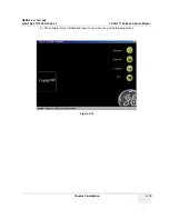
Connect the LOGIQ™
180 MP to the PC through the Image Transfer Cable -2344566.
This completes the total installation of the
Image Transfer
software.
NOTE:
To transfer images, please refer to the Operator manual.
3-5-3
Installation of Optional Accessories
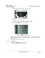
1.) Unpack the foot switch and connect it to the connector on the rear panel. (Refer Figure 3-20)
2.) Connect the VCR to a suitable power outlet. Using the BNC to BNC cable connect the Video Out
on the rear panel of LOGIQ™ 180 to the Video IN of the VCR.
3.) Connect the Video Graphic Printer (VGP) to a suitable power outlet. Using the BNC to BNC cable
connect the Video Out on the rear panel of LOGIQ™ 180 to the Video IN of the VGP.
NOTE:
Figure 3-20 Installation of Accessories
Service Port (Parallel Port)
Video out
Video in
Shutter
Foot Switch
Содержание H41542LA
Страница 2: ......
Страница 5: ...GE MEDICAL SYSTEMS DIRECTION 2317229 REVISION 3 LOGIQ 180 BASIC SERVICE MANUAL ii iii ...
Страница 160: ...GE MEDICAL SYSTEMS DIRECTION 2317229 REVISION 3 LOGIQ 180 BASIC SERVICE MANUAL 2 Index ...
Страница 161: ......


