background image

GE M

EDICAL

 S

YSTEMS


D

IRECTION

 2317229, R

EVISION

 3

LOGIQ™ 180 B

ASIC

 S

ERVICE

 M

ANUAL


Chapter 10 Quality Assurance

10 - 3

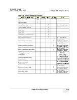
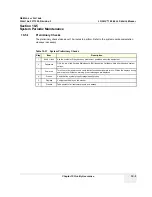
Table 10-35   Periodic Maintenance Schedule

Service at Indicated Time

Daily

Weekly

Monthly

Annually

Notes

Clean Probes

•*

* or before each use

Clean Probe Holders

Inspect AC Mains Cable

Mobile Unit Check Weekly

Inspect Cables and Connectors

Clean Console

Clean Monitor 

Inspect Wheels, Casters, brake locks 

Check Control Panel Movement

Mobile Unit Check Daily

Console Leakage Current Checks

also after corrective 
maintenance or as required by 
your facilities QA program

Peripheral Leakage Current Checks

also after corrective 
maintenance or as required by 
your facilities QA program

Surface Probe Leakage Current Checks

also after corrective 
maintenance or as required by 
your facilities QA program

 Endocavity Probe Leakage 
Current Checks

Twice

Annually

Transesphongeal Probe Leakage 
Current Checks

As Prescribed

in probe manual

Surgical Probe Leakage 
Current Checks

As Prescribed

in probe manual

Measurement Accuracy Checks

also after corrective 
maintenance or as required by 
your facilities QA program

Probe/Phantom Checks

also after corrective 
maintenance or as required by 
your facilities QA program

Содержание H41542LA

Страница 1: ...Technical Publication Direction 2317229 Revision 3 GE Medical Systems LOGIQ 180 Basic Service Manual Copyright 2002 2003 2004 by General Electric Co GE Medical Systems ...

Страница 2: ......

Страница 3: ...E L ANGLAIS C EST AU CLIENT QU IL INCOMBE DE LE FAIRE TRADUIRE NE PAS TENTER D INTERVENTION SUR LES éQUIPEMENTS TANT QUE LE MANUEL SERVICE N A PAS éTé CONSULTé ET COMPRIS LE NON RESPECT DE CET AVERTISSEMENT PEUT ENTRAîNER CHEZ LE TECHNICIEN L OPéRATEUR OU LE PATIENT DES BLESSURES DUES à DES DANGERS éLECTRIQUES MéCANIQUES OU AUTRES DIESES KUNDENDIENST HANDBUCH EXISTIERT NUR IN ENGLISCHER SPRACHE FA...

Страница 4: ...NUAIS NOUTRO IDIOMA é DA RESPONSABILIDADE DO CLIENTE FORNECER OS SERVIç OS DE TRADUç ã O Nã O TENTE REPARAR O EQUIPAMENTO SEM TER CONSULTADO E COMPREENDIDO ESTE MANUAL DE ASSISTêNCIA TéCNICA O Nã O CUMPRIMENTO DESTE AVISO PODE POR EM PERIGO A SEGURANç A DO TéCNICO OPERADOR OU PACIENTE DEVIDO A CHOQUES ELéTRICOS MECâ NICOS OU OUTROS IL PRESENTE MANUALE DI MANUTENZIONE è DISPONIBILE SOLTANTO IN INGL...

Страница 5: ...GE MEDICAL SYSTEMS DIRECTION 2317229 REVISION 3 LOGIQ 180 BASIC SERVICE MANUAL ii iii ...

Страница 6: ...TOR STATEMENT FOR USA ONLY All electrical Installations that are preliminary to positioning of the equipment at the site prepared for the equipment shall be performed by licensed electrical contractors Other connections between pieces of electrical equipment calibrations and testing shall be performed by qualified GE Medical Systems personnel In performing all electrical work on these products GE ...

Страница 7: ...2 1 to 2 6 3 Chapter 7 Diagnostics Troubleshooting pages 7 1 to 7 14 3 Important Precautions pages i to iv 3 Chapter 3 Installation pages 3 1 to 3 26 3 Chapter 8 Replacement Procedures pages 8 1 to 8 2 3 Rev History LOEP pages v to vi 3 Chapter 4 Functional Checks pages 4 1 to 4 12 3 Chapter 9 Replacement Parts pages 9 1 to 9 16 3 Table of Contents pages 1 to 12 3 Chapter 5 Theory pages 5 1 to 5 1...

Страница 8: ...GE MEDICAL SYSTEMS DIRECTION 2317229 REVISION 3 LOGIQ 180 BASIC SERVICE MANUAL iv vi This page was intentionally left blank ...

Страница 9: ...ns 1 4 Product Icons 1 5 Safety Considerations 1 7 Introduction 1 7 Human Safety 1 7 Mechanical Safety 1 8 Electrical Safety 1 8 Labels Locations 1 9 Dangerous Procedure Warnings 1 14 Lockout Tagout Requirements For USA Europe Only 1 14 Classification 1 14 EMC EMI and ESD 1 15 Electromagnetic Compatibility EMC 1 15 CE Compliance 1 15 EMC Performance 1 15 Notice Upon Installation of Product 1 15 Ge...

Страница 10: ...nts 2 1 Lighting 2 2 Electrical Requirements 2 2 LOGIQ 180 Power Requirements 2 2 Site Circuit Breaker 2 2 Site Power Outlets 2 2 Unit Power Plug 2 2 Power Stability Requirements 2 2 EMI Limitations 2 3 Probes Environmental Requirements 2 4 Time and Manpower Requirements 2 4 Facility Needs 2 5 Purchaser Responsibility 2 5 Required Features 2 5 Desirable Features 2 6 Checklist for Installation 2 6 ...

Страница 11: ...mpleting the Installation 3 10 Transducer Connection 3 10 Installation of LOGIQ 180 to PC Image Transfer Software 3 10 Pre requisites 3 10 Installation of Optional Accessories 3 16 Adjustment of Monitor Brightness Contrast 3 17 Adjustment of System Clock Date Hospital Name OB Version 3 17 System Configuration 3 18 System Specifications 3 18 Physical Dimensions 3 18 Front View 3 19 Weight without P...

Страница 12: ...GE MEDICAL SYSTEMS DIRECTION 2317229 REVISION 3 LOGIQ 180 BASIC SERVICE MANUAL 4 Table of Contents Paperwork 3 27 User Manual s 3 27 Product Locator Card 3 27 ...

Страница 13: ...dures 4 2 Power On Boot Up 4 2 System Boot UP Shutdown 4 2 Power Up 4 3 Power Shutdown 4 3 Functional Check Procedures 4 4 Power Up Monitor Display Convex Probe 4 5 Basic Controls 4 6 Phantom Check 4 8 Diagnostics 4 9 Power On Diagnostics 4 9 Service Diagnostics 4 9 Software Configuration Checks 4 10 Peripheral Checks 4 10 Patient contact tools 4 11 Probe Connectors Check 4 11 ...

Страница 14: ...ter 5 5 1 Block Diagram 5 2 PCB Nomenclature 5 5 Dip Switch Setting 5 5 FEB Board 5 5 CPU Board 5 6 Wiring Diagrams 5 7 Power Distributor Power Supply Wiring Diagram 5 7 Cable Assembly Diagrams 5 9 Functional Subsystems 5 12 Front End Board 5 12 DSC Board 5 12 CPU Board 5 12 Peripherals 5 12 Video Specifications 5 13 Rear Panel Signal List 5 13 ...

Страница 15: ... SERVICE MANUAL Table of Contents 7 CHAPTER 6 Service Adjustments Overview 6 1 Purpose of Chapter 6 6 1 Power Supply Adjustment 6 2 Caution 6 2 Access to Adjustments 6 2 Caster Brake Function Adjustment 6 3 Monitor Adjustments 6 4 Jumper and Dip Switch Setting 6 5 ...

Страница 16: ...ntents CHAPTER 7 Diagnostics Overview 7 1 Purpose of Chapter 7 7 1 Power On Diagnostics 7 2 Service Diagnostics 7 2 CPU Board Tests 7 3 DSC Board Tests 7 6 FEB Test for LOGIQ 180 V7 0HC 7 7 Keyboard Tests 7 7 Monitor Test 7 9 Key Operation History 7 12 Error Reporting 7 13 Error Reporting 7 13 ...

Страница 17: ...GE MEDICAL SYSTEMS DIRECTION 2317229 REVISION 3 LOGIQ 180 BASIC SERVICE MANUAL Table of Contents 9 CHAPTER 8 Replacement Procedures Overview 8 1 Purpose of Chapter 8 8 1 ...

Страница 18: ...SERVICE MANUAL 10 Table of Contents CHAPTER 9 Replacement Parts Overview 9 1 Purpose of Chapter 9 9 1 Monitor 9 3 Casters 9 4 Covers 9 5 Probe Port and Front Panel 9 7 Keyboard 9 8 Circuit Board Assembly 9 10 Power Supply and TRANS Assy 9 11 Options 9 13 Cables 9 14 ...

Страница 19: ...ic Maintenance 10 4 System Periodic Maintenance 10 5 Preliminary Checks 10 5 Functional Checks See Also Chapter 4 10 6 System Checks 10 6 Peripheral Option Checks 10 7 Input Power 10 7 Mains Cable Inspection 10 7 Cleaning 10 7 General Cleaning 10 7 Physical Inspection 10 8 Probe Maintenance 10 8 Probe Related Checks 10 8 Basic Probe Care 10 8 Basic Probe Cleaning 10 9 Using a Phantom 10 9 Electric...

Страница 20: ...ANUAL 12 Table of Contents Data Sheet for Chassis Source Leakage Current 10 16 Probe Leakage Current Test 10 17 Definition 10 17 Generic Procedure 10 17 General procedure 10 17 Data Sheet for Transducer Source Leakage Current 10 18 When There s Too Much Leakage Current 10 19 ...

Страница 21: ...ure with installation checklist 4 Chapter 4 Functional Checks Contains functional checks that must be performed as part of the installation or as required during servicing and periodic maintenance 5 Chapter 5 Theory Contains block diagrams and functional explanations of the electronics 6 Chapter 6 Service Adjustments Contains instructions on how to make any available adjustments to the LOGIQ 180 7...

Страница 22: ...OGIQ 180 Models Covered by this Manual 1 1 5 Purpose of Operator Manual s The Operator Manual s should be fully read and understood before operating the LOGIQ 180 and also kept near the unit for quick reference Table 1 2 LOGIQ 180 Models Covered in this Manual Part Number Description Comments H41542LA LOGIQ 180 220V 240V LOGIQ 180 for China H41542LB LOGIQ 180 220V 240V LOGIQ 180 for Europe H41542L...

Страница 23: ... precautionary message Known or potential hazards are labeled in one of three ways NOTE Notes provide important information about an item or a procedure Be sure to read the note the information contained in a NOTE can often save you time or effort DANGER Danger is used to indicate the presence of a hazard that will cause severe personal injury or death if the instructions are ignored WARNING WARNI...

Страница 24: ...ut this chapter In addition to text several different graphical icons symbols may be used to make you aware of specific types of hazards that could cause harm Other hazard icons make you aware of specific procedures that should be followed Table 1 3 Standard Hazard Icons ELECTRICAL MECHANICAL RADIATION LASER HEAT PINCH Table 1 4 Standard Icons Indicating a Special Procedure to be Used AVOID STATIC...

Страница 25: ... PCG connector Device Listing Certification Labels Laboratory logo or labels denoting conformance with industry safety standards such as UL or IEC Rear of console CAUTION This unit weighs Special care must be used to avoid This precaution is intended to prevent injury that may result if one person attempt to move the unit considerable distances or on an incline due to the weight of the unit On the...

Страница 26: ...ates the protective earth grounding terminal Non Ionizing Radiation indicates that the system applies RF energy Rear of console near power inlet Date of manufacture The date could be a year year and month or year month and day as appropriate See ISO 8601 for date formates Rating Plate Catalog or model number Rating Plate Serial number Rating Plate Equipment Class II For products not relying protec...

Страница 27: ...mage A damaged probe has to be discarded It cannot be repaired or reused Do not allow the lens to come into contact with a sharp object or to be knocked against an object 5 Do not place liquids on or above the console If the liquid spills it may come in to contact with live parts and can cause an electric shok This system contains no operator serviceable components To prevent shock do not re move ...

Страница 28: ...for this equipment should not be shared with other types of equipment Both the system power cable and the power connector meet international electrical standards WARNING WARNING When the unit is raised for a repair or moved along any incline use extreme caution since it may become unstable and tip over WARNING WARNING Ultrasound probes are highly sensitive medical instruments that can easily be da...

Страница 29: ...GE MEDICAL SYSTEMS DIRECTION 2317229 REVISION 3 LOGIQ 180 BASIC SERVICE MANUAL Chapter 1 Introduction 1 9 1 3 5 Labels Locations Figure 1 1 Console Labels Location for China ...

Страница 30: ...GE MEDICAL SYSTEMS DIRECTION 2317229 REVISION 3 LOGIQ 180 BASIC SERVICE MANUAL 1 10 Section 1 3 Safety Considerations Labels Locations cont d Figure 1 2 Console Labels Location Europe ...

Страница 31: ...GE MEDICAL SYSTEMS DIRECTION 2317229 REVISION 3 LOGIQ 180 BASIC SERVICE MANUAL Chapter 1 Introduction 1 11 Labels Locations cont d Figure 1 3 Console Labels Location India ...

Страница 32: ...GE MEDICAL SYSTEMS DIRECTION 2317229 REVISION 3 LOGIQ 180 BASIC SERVICE MANUAL 1 12 Section 1 3 Safety Considerations Labels Locations cont d Figure 1 4 Console Labels Location Korea ...

Страница 33: ...GE MEDICAL SYSTEMS DIRECTION 2317229 REVISION 3 LOGIQ 180 BASIC SERVICE MANUAL Chapter 1 Introduction 1 13 Labels Locations cont d Figure 1 5 Console Labels Figure 1 6 Printer Panel label ...

Страница 34: ...otective earth conductor in the fixed wiring of the installation in such a way that ACCESSIBLE METAL PARTS cannot become LIVE in the event of a failure of the BASIC INSULATION 2 Type BF EQUIPMENT Type B EQUIPMENT with a F TYPE isolated applied part providing a degree of protection against electric shock to such a degree that the allowable PATIENT LEAKAGE CURRENT under SINGLE FAULT CONDITIONS is no...

Страница 35: ...on following all comments noted in this service manual is required in order to achieve full EMC performance 1 4 3 EMC Performance All types of electronic equipment may characteristically cause electromagnetic interference with other equipment either through air or connecting cables The term EMC Electromagnetic Compatibility indicates capability of the equipment which curbs electromagnetic influenc...

Страница 36: ... reduced by positioning other equipment far away from the system 2 Electromagnetic interference may be reduced by changing the relative location installation angle of the system and other equipment 3 Electromagnetic interference may be reduced by changing wiring locations of power signal cables of other equipment 4 Electromagnetic influence may be reduced by altering the path of power supply for o...

Страница 37: ...ne Number USA Canada GE Medical Systems Ultrasound Service Engineering 4855 W Electric Avenue Milwaukee WI 53219 Customer Answer Center 1 800 437 1171 1 800 682 5327 1 262 524 5698 Fax 1 414 647 4125 Latin America GE Medical Systems Ultrasound Service Engineering 4855 W Electric Avenue Milwaukee WI 53219 Customer Answer Center 1 262 524 5300 1 262 524 5698 Fax 1 414 647 4125 Europe GE Ultraschall ...

Страница 38: ...UAL 1 18 Section 1 5 Customer Assistance 1 5 2 System Manufacturer Table 1 7 System Manufacturer Manufacturer FAX Number GE Medical Systems China Co Ltd No 19 Changjiang Road Wuxi National Hi Tech Development Zone Jiangsu P R China 214028 TEL 86 510 5225888 FAX 86 510 5226688 ...

Страница 39: ... of this section to help determine whether the proper planning and preparation is accomplished before the actual equipment installation is scheduled CONTENTS IN CHAPTER 2 Section 2 2 General Console Requirements 2 2 1 Console Environmental Requirements Table 2 8 Contents in Chapter 2 Section Description Page Number 2 1 Overview 2 1 2 2 General Console Requirements 2 1 2 3 Facility Needs 2 5 Table ...

Страница 40: ... and test equipment needed to support this unit must also be present within 1 m 3 2 ft of the unit Electrical installation must meet all current local state and national electrical codes 2 2 2 4 Unit Power Plug If the unit arrives without a power plug or with the wrong plug you must contact your GE dealer or the installation engineer must supply what is locally required 2 2 2 5 Power Stability Req...

Страница 41: ...ated on the EMC label However there is no guarantee that interference will not occur in a particular installation Possible EMI sources should be identified before the unit is installed Electrical and electronic equipment may produce EMI unintentionally as the result of a defect These sources include medical lasers scanners cauterizing guns computers monitors fans gel warmers microwave ovens light ...

Страница 42: ... replace the gasket Do not turn on the unit until any loose metallic part is removed Do not place labels where RF gaskets touch metal Never place a label where RF gaskets meet the unit Otherwise the gap created will permit RF leakage Or if a label has been found in such a position move the label Use GE specified harnesses and peripherals The interconnect cables are grounded and require ferrite bea...

Страница 43: ...ts of applicable electrical codes The purchaser of GE equipment must only utilize qualified personnel to perform electrical servicing on the equipment The desire to use a non listed or customer provided product or to place an approved product further from the system than the interface kit allows presents challenges to the installation team To avoid delays during installation such variances should ...

Страница 44: ...ed probe sheaths Emergency oxygen supply Storage for lines and equipment Nearby waiting room lavatory and dressing room Dual level lighting bright and dim Lockable cabinet ordered by GE for its software and proprietary manuals 2 3 4 Checklist for Installation 2 3 4 1 Checklist for Installation Table 2 13 Checklist for Installation Procedures Paragraph Initials Unpack LOGIQ 180 Section 3 2 Assemble...

Страница 45: ...rnal peripherals for electrical safety are included in this procedure Also included in this section are guidelines for transporting the unit to a new site 3 1 2 Contents IN chapter 3 3 1 3 Average Installation Time Table 3 14 Contents in Chapter 3 Section Description Page Number 3 1 Overview 3 1 3 2 Receiving and Unpacking the Equipment 3 4 3 3 Preparing for Installation 3 9 3 4 Assembling LOGIQ 1...

Страница 46: ...g 4 If safe leakage current levels are not achieved the all parts of the system must be removed from the patient vicinity before being interconnected For example the transfer of the images from the LOGIQ 180 to a personal computer which exceeds safe current limits for medical electrical equipment must be done only if both pieces of equipment are not located in the patient vicinity DANGER WHEN USIN...

Страница 47: ...in place System performance and cooling require this CAUTION OPERATOR MANUAL S The User Manual s should be fully read and understood before operating the LOGIQ 180 and kept near the unit for quick reference CAUTION ACOUSTIC OUTPUT HAZARD Although the ultrasound energy transmitted from the LOGIQ 180 probe is within AIUM NEMA standards avoid unnecessary exposure Ultrasound energy can produce heat an...

Страница 48: ...ice you to store the LOGIQ 180 packing material in undamaged condition in case of future transportation 1 Cut the two bands and two plumbum rope 2 Remove the clip by clip opening tool 3 Then open the wood box include top cover and side cover 4 Remove the plastic covers and all vinyl covers 5 Remove the option box accessories box and Manuals 6 Lift the console down then lock the casters Figure 3 8 ...

Страница 49: ...ontainer for special instructions Verify that the container is intact If not tally with the shipping list ask the carrier for unpacking instructions NOTE The Service Manual Operator Manual and Gel Bottle are wrapped in bubble sheet and are kept along the sides of the corrugated carton box Refer Illustration below for details Figure 3 10 Unpacking procedure 3 ...

Страница 50: ...king the Equipment 3 2 2 Packing Procedure 1 Clean the system then make the preparation as below a Put the top cover sheet on the system top cover b Cover the ten caps on the side cover c Clean the caster power cord d Check the accessories based on checklist Figure 3 11 Packing procedure 1 Top cover sheet Top cover ...

Страница 51: ...er the plastic sheet around the keyboard and monitor 4 Put the right side cushion and left side cushion around the console cover them with plastic sheet 5 Put the probe box and accessories box in front of the console detail in picture cover them with plastic sheet again 6 Put the middle frame and top cap around the keyboard and monitor detail in picture Figure 3 12 Packing procedure 2 Middle suppo...

Страница 52: ...edure cont d 7 Cover the whole console with the plastic bag 8 Fix the side cover and top cover with the clip 9 Attach the shipment card package label and on the position which show on the picture 10 Fix the steel band around the package then attach the clip opening tool on the position which showed on the picture Figure 3 13 Packing procedure 2 ...

Страница 53: ...cured before the unit is put into operation Section 3 4 Assembling LOGIQ 180 3 4 1 Installation of the System 1 Locate remove and unpack the probes located in the separate container 2 Make sure that system power is OFF before connecting or disconnecting the probe 3 Secure the probe to the receptacle as follows a Ensure probe twist lock lever points towards the 12 o clock position a Install probe c...

Страница 54: ...e can be used to download images from the LOGIQ 180 Service Port parallel port to the PC It can also be used to retrieve view images already stored in the PC NOTE For more details on the application of the Image Transfer Software please refer to the Operator manual 3 5 2 1 Pre requisites Hardware Software requirements For Europe Only All devices connected to the LOGIQ 180 must be CE Marked A Hardw...

Страница 55: ...ed in the EPP ECP Bi directional mode This can be done by entering into the CMOS setting of the PC If required for more details contact your local PC supplier D Software Installation 1 Before starting to install the Image Transfer software close all applications 2 For LOGIQ 180 Systems Insert CD 2347331 in the CD Drive and click Start and then click Run as shown below Figure 3 14 ...

Страница 56: ...ASIC SERVICE MANUAL 3 12 Section 3 5 Completing the Installation 3 Now type the Respective Drive Letter E g F in95 98 Setup exe as shown below and click OK Figure 3 15 For Systems With Win95 98 ME Operating Systems For Systems With WinNT 2000 Operating Systems ...

Страница 57: ... 180 BASIC SERVICE MANUAL Chapter 3 Installation 3 13 4 A warning screen will appear asking to close all other applications 5 Click OK if other applications are closed else click Exit Set up close all programs and go through steps 2 to 4 again Figure 3 16 ...

Страница 58: ... Installation screen appears To change the directory click on change directory and select the desired directory Click on the installation button to continue with Installation 7 Next you will get the following screen indicating the completion of the installation Click OK to come out of the installation set up Figure 3 17 Figure 3 18 ...

Страница 59: ...E MEDICAL SYSTEMS DIRECTION 2317229 REVISION 3 LOGIQ 180 BASIC SERVICE MANUAL Chapter 3 Installation 3 15 8 The software is fully installed and ready to use when you get the following screen Figure 3 19 ...

Страница 60: ...tallation of Optional Accessories 1 Unpack the foot switch and connect it to the connector on the rear panel Refer Figure 3 20 2 Connect the VCR to a suitable power outlet Using the BNC to BNC cable connect the Video Out on the rear panel of LOGIQ 180 to the Video IN of the VCR 3 Connect the Video Graphic Printer VGP to a suitable power outlet Using the BNC to BNC cable connect the Video Out on th...

Страница 61: ...d be adjusted according to the lighting in the room 3 5 5 Adjustment of System Clock Date Hospital Name OB Version Press CTRL S 1 ENTER an Installation Setup window appears Set the system Clock Date Hospital Name and OB Version These settings can be modified by using the CONTROL S 1 key if required Refer Section Control Keys of the User Manual for more details CAUTION Functional checks in Chapter ...

Страница 62: ... 18 Section 3 6 System Configuration Section 3 6 System Configuration 3 6 1 System Specifications 3 6 1 1 Physical Dimensions The physical dimensions of the LOGIQ 180 unit are summarized in Table 3 1 Table 3 1 Physical Dimensions of LOGIQ 180 Height Width Depth Unit 145 40 66 3 cm ...

Страница 63: ...GE MEDICAL SYSTEMS DIRECTION 2317229 REVISION 3 LOGIQ 180 BASIC SERVICE MANUAL Chapter 3 Installation 3 19 3 6 1 2 Front View Figure 3 21 Overall Dimensions ...

Страница 64: ...standards This receptacle should have International Electro technical Commission IEC approval or equivalent Table 3 2 Weight of LOGIQ 180 Model Weight kg Weight lbs LOGIQ 180 72 2 163 17 Table 3 3 Electrical Specifications for LOGIQ 180 GEMS P N Voltage Tolerances Current Frequency H41542LA 220 240 VAC 10 1 9 2 0 A Max 50 Hz H41542LB 220 240 VAC 10 1 9 2 0 A Max 50 Hz H41542LC 220 240 VAC 10 1 9 2...

Страница 65: ...age Operation Requirements 3 6 3 Optional Peripherals LOGIQ 180 peripherals and accessories can be properly connected using the connectors on the rear panel of the LOGIQ 180 system External Optional Peripherals VCR Sony SVO 9500MD VGP Sony UP 895MDW MD SYN Parameter Storage Operation Temperature Deg C Deg F 10 to 60 14 to 140 10 40 50 to 104 Atmospheric Pressure hPa 700 to 1060 700 to 1060 Humidit...

Страница 66: ...devices connected to the LOGIQ 180 must be CE Marked Located on the panel are video input output connectors footswitch connector shutter connector power connector control connections for Video Graphic Printer and Service Port Parallel Port Figure 3 22 Optional Peripherals Service Port Parallel Port Video out Video in Shutter Foot Switch ...

Страница 67: ... 23 Connector Female D type 25 Pin on the Rear Panel Table 3 6 Parallel Port 25 Pin Connector Details Pin Number Signal Pin1 STROBE WRITE Pin 2 DATA 1 Pin 3 DATA 2 Pin 4 DATA 3 Pin 5 DATA 4 Pin 6 DATA 5 Pin 7 DATA 6 Pin 8 DATA 7 Pin 9 DATA 8 Pin 10 ACKNLG Pin 11 Busy Pin 12 PE Pin 13 SLCT Pin 14 Not Connected Pin 15 ERROR Pin 16 INIT Pin 17 SELECT IN Pin 18 GND Pin 19 GND Pin 20 GND Pin 21 GND Pin...

Страница 68: ...NC cable Video IN to the Video OUT located on the rear panel of the system also establish shutter with Mini Jack cable if required Model Sony UP 890MD CE MDG or UP 895MDW MD SYN Mitsubishi P91E D Pin Assignment of Mini Jack controlling VGP E Video Casette Recorder Connect the VCR Sony SVO 9500MD H4120SR for NTSC and Sony SVO 9500MDP E11801AA for PAL System to the Video IN socket in the rear panel ...

Страница 69: ... the LOGIQ 180 User Manual for Probes and intended use Table 3 7 Available Probes Probe Type Part No Catalog No Freq in MHz Radius of Curvature FOV C36 2107922 H45252CF 3 5 50mm 68 C55 2107925 H45252CE 5 0 40mm 68 E72 2107928 H45252MT 6 5 10mm 114 L76 2107910 H45252HP 7 5 60mm C31 2175994 H45252CS 3 5 13mm 85 CAUTION Use only approved probes peripherals or accessories ...

Страница 70: ...08 X 472 Horizontal Timing Video Amplitude SL Parameter NTSC PAL 1 Total H Line Time 63 556 micro sec 64 00 micro sec 2 H Sync Pulse Width 4 725 micro sec 4 68 micro sec 3 Back Porch 4 725 micro sec 4 68 micro sec 4 Total Active H line time 52 64 micro sec 52 07 micro sec 5 Front Porch 1 46 micro sec 1 49 micro sec 6 Video Amplitude back porch to peak 0 7Vpp 0 7Vpp 7 Sync Amplitude back porch to p...

Страница 71: ...tions are available during the operation and service of the complete system 3 7 1 User Manual s Check that the correct User Manual s per software sw revision for the system is included 3 7 2 Product Locator Card Fill out proper customer information on the Product Locator Installation Card Refer to Illustration below Mail this Installation Card Product Locator to the address corresponding to your p...

Страница 72: ...GE MEDICAL SYSTEMS DIRECTION 2317229 REVISION 3 LOGIQ 180 BASIC SERVICE MANUAL 3 28 Section 3 7 Paperwork This page was intentionally left blank ...

Страница 73: ...he LOGIQ 180 scanner diagnostics by using the built in service software and power supply adjustments For remaining functional checks please refer to the LOGIQ 180 Operator s Manual CONTENTS IN CHAPTER 4 Table 4 8 Contents in chapter 4 Section Description Page Number 4 1 Overview 4 1 4 2 General Procedures 4 2 4 3 Functional Check Procedures 4 4 4 4 Diagnostics 4 9 4 5 Software Configuration Checks...

Страница 74: ...cled too quickly 4 2 1 1 System Boot UP Shutdown Purpose This is a description on how to Shut Down Power UP the system CAUTION SYSTEM REQUIRES ALL COVERS Operate this unit only when all board covers and frame panels are securely in place The covers are required for safe operation good system performance and cooling purposes NOTICE Lockout Tagout Requirements For USA only Follow OSHA Lockout Tagout...

Страница 75: ...buted to the Fan Control panel Monitor Internal and External I O s Boards Peripherals Back End Processor starts and its software code is distributed to initiate the scanner Power Up Display Comes Up Refer figure 4 29 4 2 1 3 Power Shutdown 1 Switch OFF the ON OFF at the Front of the system 2 Disconnect the Mains Power Cable if needed Figure 4 27 Mains Circuit Breaker and Mains Power Cable Figure 4...

Страница 76: ...the system is required Turn ON the LOGIQ 180 system The 2 LEDS External Video and Freeze blink and go off The system beeps once and runs a self test The Monitor displays the following Refer figure 4 29 for details 1 B Mode Image appears 2 Gray Scale Display 3 Horizontal Scale Marker 4 Vertical Scale Marker 5 Hospital Name If previously entered 6 Date 7 Time 8 Probe Type 9 Focus Marker on vertical ...

Страница 77: ...E MEDICAL SYSTEMS DIRECTION 2317229 REVISION 3 LOGIQ 180 BASIC SERVICE MANUAL Chapter 4 Functional Checks 4 5 4 3 1 Power Up Monitor Display Convex Probe Figure 4 29 Power Up Monitor Display Convex Probe ...

Страница 78: ...e 4 30 The M Line cursor should follow the trackball movement and the real time image varies on the M Mode display Only M Mode image appears on the screen Press B Mode Key to exit M Mode Press Freeze key The image will freeze Press ATO ATO Automatic Tissue Optimization optimizes the image based upon a specified Region Of Interest ROI or anatomy within the display ATO Gray scale map is available on...

Страница 79: ... Archive screen appears with option menu at the bottom Select the image using the trackball Use Dynamic Range to page up down in the Image Archive screen Press 1 to View the selected image Press 2 to Clear the selected image Press 3 to Clear All the stored images Press 4 to Sort the images by name or date To Exit Image Archive press Freeze TGC The TGC is used to adjust the Gain at a specific depth...

Страница 80: ...GIQ 180 BASIC SERVICE MANUAL 4 8 Section 4 3 Functional Check Procedures Basic Controls Continued 4 3 3 Phantom Check RMI Phantom 403GS Part No 2113294 to be used to check image quality and proper functioning of the system Figure 4 30 B M Mode Display ...

Страница 81: ...evel The diagnostic tools provides a pop up menu to enable selection of various tests to test various blocks on the system 4 4 1 Power On Diagnostics The power on diagnostics or self tests are run every time the system is booted This self tests include testing the validity of the system software through EPROM checksum test and testing the system RAM It checks whether the keyboard and the trackball...

Страница 82: ...rrect Re enter the correct Location Name Table 4 11 Peripheral checks Step Check Expected Result s If Not Remedy 1 Press Freeze Key to stop image acquisition 2 Press RECORD Key on the Control panel The image displayed on the screen is printed on B W Video Graphic Printer 3 Press SHIFT RECORD Key on the Control Panel To image or report page displayed on the screen is printed on the Parallel Printer...

Страница 83: ... so that it is not resting on the floor CAUTION Do not allow the probe head to hang freely Impact to the probe head may result in irreparable damage To connect a probe 3 Rotate the lock handle counter clockwise to the Vertical position to unlock the connector Remove the connector from the port Ensure that the probe head is clean before placing the probe in its storage case To disconnect probes The...

Страница 84: ...Horizontal position to lock in place Position the probe cable so that it is not resting on the floor CAUTION Do not allow the probe head to hang freely Impact to the probe head may result in irreparable damage It will display the Probe name on the Screen WARNING WARNING Probes can be connected at any time whether the unit is on or off WARNING WARNING Do NOT touch the patient and any of the connect...

Страница 85: ...ains LOGIQ 180 s system concepts component arrangement and subsystem function It also describes the Power Distribution System PDS and probes CONTENTS IN CHAPTER 5 Table 5 13 Contents in Chapter 5 Section Description Page Number 5 1 Overview 5 1 5 2 Block Diagram 5 2 5 3 Wiring Diagrams 5 7 5 4 Functional Subsystems 5 12 5 5 Video Specifications 5 13 5 6 Rear Panel Signal List 5 13 ...

Страница 86: ...ANUAL 5 2 Section 5 2 Block Diagram Section 5 2 Block Diagram Block Diagram Figure 5 31 Block Diagram LOGIQ 180 General DSC Board External I O Display Probe Monitor VCR Patient I O Patient Isolated Sensors Printers Control CPU Board TX RX Front End Board FEB BUS Relay Board ...

Страница 87: ...eo Signal Digital Signal 120V 5V 12V 12V HV PCB HV MUX TransmitB uffer Driver 16 TPG2 Rel ay B oar d DSP FPG A FEB B us t o DSC Frame Avera ge S RAM RX I F Pre Am p 16 2 1 Summer VC A ADC I F ADC 16 8 8 OQ CO M SO 2 DAC C LO CK G enerat or 40M Hz 30 M Hz Data C l k FEB B oar d HV 120V 135V PS HV Max 64 16 16 2 3 OQ CARD O cta l Q uad C hannel Asi c Receivin g Del ay CO M SO C O M pl ex M ode M i d...

Страница 88: ...or LOGIQ 180 KEYBOARD TRACKBALL GAIN CONTROL NVRAM 5v FLASH MEMORY 16 image capacity SCAMP II System controller RADISYS R380EX System Controller FLS CARD 96 IMAGES OPTIONAL Used for PC based debug on CPU serial port RS232 Parallel Connectivity Parallel Port Printer or PC CINE MEMORY 32 FRAME STD 64 FRAMES OPT FEB IF Block FEB Bus AFM CP U DSC LOG I Q 180 3 10 ...

Страница 89: ... End Board For LOGIQ 180 V7 0HC PDB Power Distributor PCB For LOGIQ 180 V7 0HC RLB Relay Board For LOGIQ 180 V7 0HC CAUTION The Settings are valid only when jumper JP1 and JP20 are in Test mode and is used for PCB testing in the production line The equipment at the customer site should have JP1 and JP20 in normal mode which makes DIP switch S1 ineffective Table 5 15 S1 1 Probe Type 0 2 Probe Type ...

Страница 90: ...vex C31 010101 15 3 5MHz Table 5 17 CPU Board SW1 SW3 Location Switch No Settings SW1 SW3 2 0 STDOUT is LOGIQ 180 Display 1 STDOUT Standard Output AUX PC 3 0 STDIN Standard Input is AUX PC 1 STDIN is LOGIQ 180 Keyboard 4 0 NTSC Setup 1 PAL Setup 5 0 2MB DRAM 1 512KB DRAM 6 7 8 000 Debug Monitor 100 Application Ultrasound Mode 001 Service Diagnostics Table 5 18 Location Switch No Settings SW2 S1 0 ...

Страница 91: ...iring Diagram Figure 5 34 Power Distributor Power Supply Wiring Diagram CA 6 CA 4 CA 7 CA 8 CA 9 CA 16 CA 15 Ferri te Core Con DSC Ana Pwr Con Fan CON Monitor CA 29 12 10 6 5 7 17 16 3 15 20 19 FEB CA 28 CRT PCB CON1 Power Supply to PDB Pins 1 2 4 8 9 11 13 14 18 are not connected in Con1 of PDSTR 1 2 3 4 5 6 7 8 9 10 11 12 13 14 15 16 Conn_SMPS Conn_Pwr_Sense L N G ...

Страница 92: ...ND PWR DSTR CON Monitor to CRT 1 GND 2 NC 2 GND 2 12V 3 D GND 3 GND 4 NC 4 5V 5 C GND 5 5V 6 12V 6 GND 7 C GND PWR DSTR CON DSC to DSC CON3 1 5V 8 NC 2 GND 9 NC 3 12V 10 12V 4 GND 11 NC 5 12V 12 12V 6 GND 13 NC PWR DSTR CON FAN to FAN 1 _ 14 NC 2 12V 15 D GND 3 GND 16 A GND PDB to FEB 1 9V 17 A GND 2 GND 18 NC 3 5V 19 5V 4 GND 20 5V 5 GND PWR DSTR CON 2 1 5V 6 GND 2 GND 7 12V 3 5V 8 GND 4 GND 9 9V...

Страница 93: ...STEMS DIRECTION 2317229 REVISION 3 LOGIQ 180 BASIC SERVICE MANUAL Chapter 5 Theory 5 9 5 3 0 2 Cable Assembly Diagrams Figure 5 35 Cable Assembly Wiring Diagram TO CHASSIS 22 AWG Black 300mm TO KBD BASE PLATE CA 23 ...

Страница 94: ... Diagrams Cable Assembly Diagrams Continued Figure 5 35 40 PIN 1 2 PITCH CABLE 15 CMS 40 PIN 1 2 PITCH CABLE 15 CMS TO TRCTL CON 4 TO CPU BD CON 3 TO TRCTL CON 3 TO DSC CON 5 100 PIN 1 2 PITCH CABLE 5 cms FROM DSC CON6 TO CPU CON4 CA 05 14 PIN IDC CABLE 75 cms FROM KBD CON1 TO CPU CON5 CA 07 CA 18 CA 06 ...

Страница 95: ...317229 REVISION 3 LOGIQ 180 BASIC SERVICE MANUAL Chapter 5 Theory 5 11 Cable Assembly Diagrams Continued Figure 5 35 Rear Panel FROM TGC TO TRCTL CN10 CA 04 CA 06 PARALLEL PORT CPU CN6 25 PIN IDC CABLE 75 cms 10 PIN IDC CABLE 80 cms ...

Страница 96: ... 5 4 3 CPU Board CPU Board Controls the overall system function including man machine interface It also has an Overlay graphics controller which generates Overlay Graphics Text for the screen The Overlay data output goes to the DSC Block The CPU performs the following functions 1 RTC for time and date 2 DRAM for intermediate data storage 3 EPROM for program memory 4 Address Decoder for control sig...

Страница 97: ...NUAL Chapter 5 Theory 5 13 Section 5 5 Video Specifications Refer to Section section 3 6 6 on page 26 for more details about the Video Specifications Section 5 6 Rear Panel Signal List Refer to Section section 3 6 4 on page 23 for more details about the rear panel signal list ...

Страница 98: ...GE MEDICAL SYSTEMS DIRECTION 2317229 REVISION 3 LOGIQ 180 BASIC SERVICE MANUAL 5 14 Section 5 6 Rear Panel Signal List This page was intentionally left blank ...

Страница 99: ...Chapter 6 This section describe how to test and adjust the scanner These tests are optional You may use them to check the system for errors CONTENTS IN CHAPTER 6 Table 6 20 Contents in Chapter 6 Section Description Page Number 6 1 Overview 6 1 6 2 Power Supply Adjustment 6 2 6 3 Caster Brake Function Adjustment 6 3 6 4 Monitor Adjustments 6 4 6 5 Jumper and Dip Switch Setting 6 5 ...

Страница 100: ...s two power supply modules HVPS Assy LVPS Assy 6 2 1 Caution 6 2 2 Access to Adjustments For more information on how to remove the SMPS Assy FRU No 703 please refer to the section 8 3 46 CAUTION To avoid injury of electrical hazard disconnect the main power cable from the power outlet when adjusting the power supply Figure 6 36 Remove the SMPS Assy Figure 6 37 HVPS Assy and LVPS Assy SMPS Assy ...

Страница 101: ...er Brake Function Adjustment The LOGIQ 180 contains front brake lock adjusters They are separately adjusted using the same method Press the brake lock adjuster and tighten it securely Figure 6 38 Locations of Brake Lock Adjusters Figure 6 39 Adjusting the Brake Front Brake Lock Adjuster Rear Brake Lock Adjuster Caster Lock Lever ...

Страница 102: ...ntrast and brightness 1 Turn the Knob for brightness Turn clockwise counter clockwise to increase decrease brightness 2 Turn the knob for contrast Turn clockwise counter clockwise to increase decrease contrast NOTE After readjusting the monitor s Contrast and Brightness readjust all preset and peripheral settings Figure 6 40 Monitor adjustment Brightness Contrast ...

Страница 103: ...ASIC SERVICE MANUAL Chapter 6 Service Adjustments 6 5 Section 6 5 Jumper and Dip Switch Setting NOTE Ensure that the Dip Switch 3 SW3 4th switch of CPU Assy is set to NTSC or PAL If ON it is PAL if OFF it is NTSC Figure 6 41 CPU Dip Switch Setting for NTSC PAL ...

Страница 104: ...GE MEDICAL SYSTEMS DIRECTION 2317229 REVISION 3 LOGIQ 180 BASIC SERVICE MANUAL 6 6 Section 6 5 Jumper and Dip Switch Setting This page was intentionally left blank ...

Страница 105: ...run at the application level The LOGIQ 180 System service diagnostics comprises of 1 Self test or power on diagnostics 2 Service diagnostic tools The self test or power on diagnostics are run every time the system is booted The service diagnostic tools include test procedures for testing the system at PCB level as well as block level The diagnostic tools provides a pop up menu to enable selection ...

Страница 106: ...ns NOTE Power on Diagnostics works only when the system is in application imaging mode and not while on service diagnostics The application mode is controlled by DIP Switch SW1 SW3 6 7 8 on the CPU which is set to ON OFF OFF respectively which is the normal setting For more details refer section section 5 2 2 2 on page 6 7 2 1 Service Diagnostics Press CTRL S Enter keys on the keyboard to enter th...

Страница 107: ...uted sum is compared against zero If the resulting sum is non zero the test is reported to have failed Read Write Memory Test The Read Write memory on the CPU Board is tested by filling the memory with test patterns and reading them back and validating the read data If any of the memory byte does not contain the expected data it is declared as faulty Graphics Memory Test The overlay or the graphic...

Страница 108: ... key to exit the Graphics Test NVRAM Test When this test is selected the following will appear NOTE WRITING SUCCESSFUL and READING SUCCESSFUL indicate NVRAM test is Passed Figure 7 44 Graphics Test Figure 7 45 NVRAM TEST NVRAM TEST START OF NVRAM 0X400000 END OF NVRAM 0X403fff TEST LOCATION 0X403f00 TO 403fff WRITING TO NVRAM WRITING IS COMPLETED READING FROM THE NVRAM NVRAM TEST PASSED NOTE NON V...

Страница 109: ... archive status from flash assy This option has been provided to facilitate the interchange of Flash assy cards between CPU boards The CPU soft ware stores and keeps updating status information on all available flash image slots This status info is stored in the NVRAM When a flash assy is inserted the status info is stored in the NVRAM will not indicate the true status anymore When we run this opt...

Страница 110: ...ts When this Option is selected following menu appears All Tests This option is used to run all tests in the menu Image Memory Test The image memory is tested in the same way as the memories on the CPU board Cine Memory Test All the Cine Frames have been tested one by one by writing 4 test patterns and then reading the same Main Menu This option is used to return to the main menu Quit This option ...

Страница 111: ...ress the keys on the keyboard and the pressed keys are highlighted on the screen This is a toggle operation NOTE During Keys Test Press Ext Video at the last Pressing Ext Video key interrupts the test and return to main keyboard Tests Menu LEDS Test During this test FREEZE field and EXTERNAL VIDEO field will be displayed on the monitor The FREEZE and EXTERNAL VIDEO LEDs blink for a while sequentia...

Страница 112: ...VISION 3 LOGIQ 180 BASIC SERVICE MANUAL 7 8 Section 7 2 Power On Diagnostics Keyboard Tests cont d Main Menu This option is used to return to the main menu Quit This option is used to come out of the diagnostic and enter the application mode ...

Страница 113: ...erns are displayed on the monitor when this test is enabled Please match the patterns displayed on your monitor with the given patterns figures Figure 7 49 to Figure 7 55 The Gain Knob is used for selection of patterns 1 10 To exit out of any pattern and return to the main menu press EXTERNAL VIDEO Figure 7 49 Monitor Test Figure 7 50 Monitor Test ...

Страница 114: ...GE MEDICAL SYSTEMS DIRECTION 2317229 REVISION 3 LOGIQ 180 BASIC SERVICE MANUAL 7 10 Section 7 2 Power On Diagnostics Monitor Test Contd Figure 7 51 Monitor Test Figure 7 52 Monitor Test ...

Страница 115: ...GE MEDICAL SYSTEMS DIRECTION 2317229 REVISION 3 LOGIQ 180 BASIC SERVICE MANUAL Chapter 7 Diagnostics 7 11 Monitor Test Contd Figure 7 53 Monitor Test Figure 7 54 Monitor Test ...

Страница 116: ...emory Figure 7 49 to Figure 7 51 are also available in reverse video 7 2 7 Key Operation History When this option is selected from the Main Menu the following appears indicating a maximum of 32 keys last activated The history of keys used is stored even after powered off Figure 7 55 Monitor Test Figure 7 56 Key Operation History KEY OPERATION HISTORY KEY OPERATED KEY OPERATED 1 2 3 4 5 6 7 8 9 10 ...

Страница 117: ... board When the image memory test for the DSC board fails this message is displayed THE KEYBOARD SUBSYSTEM FAILED TO RESPOND This Message is displayed during the diagnostics of the Keyboard When the keyboard firmware is not alive this message is displayed KEYBOARD NOT CONNECTED If the keyboard is not connected then this message is displayed during system boot up NO DSC FRAME FREEZE ACKNOWLEDGE Thi...

Страница 118: ...ecall screen ARCHIVE FULL This message is displayed when the store key is pressed while the archive is full PC TRANSFER STARTS PRESS CLEAR TO ABORT This message is displayed when the PC Transfer is initiated PC IS NOT READY This message is displayed when shift store is pressed without connecting the PC PC TRANSFER ERROR This message is displayed when some error occurs in the PC transfer process Ta...

Страница 119: ...REVISION 3 LOGIQ 180 BASIC SERVICE MANUAL Chapter 8 Replacement Procedures 8 1 Chapter 8 Replacement Procedures Section 8 1 Overview 8 1 1 Purpose of Chapter 8 This chapter holds replacement procedures for the following modules subsystems ...

Страница 120: ...GE MEDICAL SYSTEMS DIRECTION 2317229 REVISION 3 LOGIQ 180 BASIC SERVICE MANUAL 8 2 Section 8 1 Overview This page was intentionally left blank ...

Страница 121: ...ves you an overview of Spare Parts for LOGIQ 180 CONTENTS IN CHAPTER 9 Table 9 23 Contents in chapter 9 Section Description Page Number 9 1 Overview 9 1 9 1 1 Purpose of Chapter 9 9 1 9 1 2 Monitor 9 3 9 1 3 Casters 9 4 9 1 4 Covers 9 5 9 1 5 Probe Port and Front Panel 9 7 9 1 6 Keyboard 9 8 9 1 7 Circuit Board Assembly 9 10 9 1 8 Power Supply and TRANS Assy 9 11 9 1 9 Options 9 13 9 1 10 Cables 9...

Страница 122: ...17228 100 1 1 1 English Holder Supporter 2185704 1 1 1 1 Probe Protector L 2158045 1 1 1 1 Gel Holder 2157984 1 1 1 1 Printer Install kit 2232078 1 1 1 1 Installation Instruction Guide 2184414 1 1 1 1 English BNC cable 2183140 1 1 1 1 Shutter cable 2183139 1 1 1 1 Gel And MSDS U0403BD 1 1 1 1 96 frame cine memory hardware 2341523 1 1 1 64 frame cine memory hardware 2341524 1 1 1 Foot switch 216224...

Страница 123: ...lastic cover PAL 1 1 2379318 CRT set and Plastic cover NTSC 1 1 101 Pot Set 2341708 Bright and Contract knob 1 2 102 CRT Filter plastic 2217745 Include 2 brackets for China India Europe 1 2 103 Monitor cover set 2148195 Rear Cover of the 10 monitor 1 2 104 Tilt Assy 2341709 Rotation device under the monitor 1 2 105 Monitor Space Plate 2148197 2 White Plastic Washer 1 1 106 Filter Clamp set 2214397...

Страница 124: ...ers Figure 9 58 Casters Table 9 25 Casters Item Part Name Part No Description Qty FRU 201 Catis Caster lock 2192111 Lock Caster 2 1 202 Catis Caster swivel 2192112 swivel 2 1 203 Bumper set 2148230 including right and left bumper 1 2 204 Front Base Cover 2148217 The cover above the front caster 1 1 201 202 203 204 ...

Страница 125: ...GE MEDICAL SYSTEMS DIRECTION 2317229 REVISION 3 LOGIQ 180 BASIC SERVICE MANUAL Chapter 9 Replacement Parts 9 5 9 1 4 Covers Figure 9 59 Covers 301 302 303 304 305 306 307 ...

Страница 126: ...Label 1 2 305 Top Cover 2158086 Top plastic cover 1 1 306 Swing Arm 2191769 Swing arm device under the monitor 1 1 307 Pole Cover Assy 2148214 2 Include Cover Pole Curtain Pole 1 2 308 Pipe Assy 2338036 Included Cable Assy 1 1 309 Printer Cover 2148220 2 Plastic cover around the printer 1 2 310 Rear Handle 2148222 The handle for pushing 1 2 311 Neck Frame 2148223 2 Under the keyboard bottom cover ...

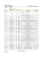
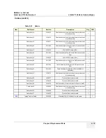
Страница 127: ...Panel Item Part Name Part No Description Qty FRU 401 Printer Bracket Assy 2347371 Include the back bracket assy P N 2346982 1 2 402 Back Breakout Assy 2346982 Print input port include breaker 1 2 403 Shield Panel 2326058 Shield panel above the relay board assy 1 2 404 Relay board Assy 2341406 Board include Bracket Probe 1 1 405 Power S W Assy 2148226 Power on off switch include the bracket 1 1 401...

Страница 128: ...GE MEDICAL SYSTEMS DIRECTION 2317229 REVISION 3 LOGIQ 180 BASIC SERVICE MANUAL 9 8 Section 9 1 Overview 9 1 6 Keyboard Figure 9 62 Keyboard 501 502 503 504 505 506 507 508 509 510 511 512 513 514 515 ...

Страница 129: ...ttom 2158940 Keyboard plastic bottom cover 1 2 506 Probe Protector S 2158046 short probe protector 1 2 507 Probe Protector L 2158045 long probe protector 1 2 508 Keyboard Assy 2330205 Keyboard component include PCB and bracket keyboard sheet 1 1 509 TGC Assy 2329699 TGC component include plastic cover and potentiometer 1 1 510 TGC top cover 2330873 6 Knobs 6 2 511 Trackball 2327348 2 penny trackba...

Страница 130: ...t Board Assembly Item Part Name Part No Description Qty FRU 601 Nest Box 2326061 the box to fix the PCB 1 2 602 Single PCB Bracket 2326052 Bracket 1 2 603 Multi PCB Bracket 2326051 Bracket 1 2 604 CPU Assy 2352811 Board 1 1 605 DSC Assy 2352813 Board 1 1 606 FEB Assy 2352815 2 Board 1 1 607 Power Distribution 2300762 Board 1 1 608 Fan 2300226 DC Fan 1 1 601 602 603 604 605 606 607 608 ...

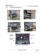
Страница 131: ...EDICAL SYSTEMS DIRECTION 2317229 REVISION 3 LOGIQ 180 BASIC SERVICE MANUAL Chapter 9 Replacement Parts 9 11 9 1 8 Power Supply and TRANS Assy Figure 9 64 Power Supply and TRANS Assy 701 702 703 704 705 706 ...

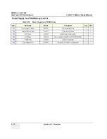
Страница 132: ...e Part No Description Qty FRU 701 Terminal Block 12 Assy 2148231 12 Pins terminal block 1 2 702 Terminal Block 6 Assy 2341371 6 Pins terminal block 1 2 703 HVPS Assy 2300757 High Voltage Power supply 1 1 704 LVPS Assy 2237916 Power supply with shield 2139739 2139726 2 1 1 705 TRNAS Assy 2160583 Isolation Transformer 1 1 706 Circuit Breaker Set 2174993 Include 1A 3A and 5A circuit breaker 1 1 ...

Страница 133: ...VICE MANUAL Chapter 9 Replacement Parts 9 13 9 1 9 Options Table 9 31 Options Item Part Name Part No Description Qty FRU 801 C36 Probe 2268634 1 802 C31 Probe 2175994 1 803 C55 Probe 2107925 1 804 E72 Probe 2274908 1 805 L76 Probe 2274906 1 806 Foot Switch 2162242 1 2 ...

Страница 134: ...bly 1 Panda Cable 9 2329709 CPU Rear Panel Parallel port cable 1 Panda Cable 10 2329710 Cable Assembly for Keyboard to trackball Assembly 1 Panda Cable 11 2329711 Cable Assembly for Keyboard to relay board Assembly 1 Panda Cable 12 2329712 KBD Chassis GDN cable 1 Panda Cable 13 2329713 Cable Assembly for Low voltage power supply to power distributor Assembly 1 Panda Cable 14 2330381 Cable Assembly...

Страница 135: ...2 connect with DH1 1 Cable Assy 19 2160476 220 240VAC output 0 8A 1 Cable Assy 64 2211955 Cable Assembly for Video Out to DH2 connect with DH1 1 Cable Assy 65 2211956 Cable Assembly for Shutter to DH2 connect with DH1 1 Cable Assy 61 2211952 Cable Assembly for Monitor to Power distributor Assembly 1 Cable Assy 13 2160472 Cable Assembly for isolation transformer to terminal block Assembly 1 Cable A...

Страница 136: ...GE MEDICAL SYSTEMS DIRECTION 2317229 REVISION 3 LOGIQ 180 BASIC SERVICE MANUAL 9 16 Section 9 1 Overview This page was intentionally left blank ...

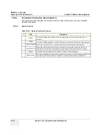
Страница 137: ...rself with the procedures before performing a task Table 10 34 Contents in Chapter 10 Section Description Page Number 10 1 Overview 10 1 10 2 Why do Periodic Maintenance 10 2 10 3 Periodic Maintenance Schedule 10 2 10 4 Tools Required 10 4 10 5 System Periodic Maintenance 10 5 10 6 Using a Phantom 10 9 10 7 Electrical Safety Tests 10 10 10 8 When There s Too Much Leakage Current 10 19 CAUTION Prac...

Страница 138: ...results corrective action and the effects of corrective action must be documented and maintained on the site Your GE service representative can help you with establishing performing and maintaining records for a quality assurance program Please contact us for coverage information and or price for service Section 10 3 Periodic Maintenance Schedule 10 3 1 How often should PMs be performed The Care M...

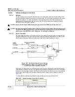
Страница 139: ...er corrective maintenance or as required by your facilities QA program Peripheral Leakage Current Checks also after corrective maintenance or as required by your facilities QA program Surface Probe Leakage Current Checks also after corrective maintenance or as required by your facilities QA program Endocavity Probe Leakage Current Checks Twice Annually Transesphongeal Probe Leakage Current Checks ...

Страница 140: ...194427P369 46 194427P373 46 194427P370 Kit includes anti static mat wrist strap and cables for 200 to 240 V system 3M 2204 Large adjustable wrist strap 3M 2214 Small adjustable wrist strap 3M 3051 conductive ground cord Anti Static Vacuum Cleaner 46 194427P278 46 194427P279 120V 230V Safety Analyzer 46 285652G1 DALE 600 KIT or equivalent for electrical tests SVHS VCR Cassette E7010GG E7010GF 60 mi...

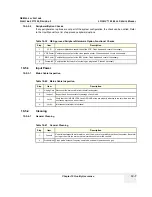
Страница 141: ... 1 Ask Listen Ask the customer if they have any problems or questions about the equipment 2 Paperwork Fill in the top of the Periodic Maintenance PM Inspection Certificate Note all probes and system options 3 Power up Turn the system power on and verify that all fans and peripherals turn on Watch the displays during power up to verify that no warning or error messages are displayed 4 Probes Verify...

Страница 142: ... basic M Mode operation Check the basic system controls that affect this mode of operation System Diagnostic Perform the Automatic Tests to verify that all boards function according to specifications Control Panel Test Perform the Control Panel Test Procedure to verify that all keyboard controls are OK This is performed by the internal PC backend processor which does a normal keyboard run through ...

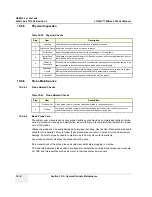
Страница 143: ...essary 3 B W Printer Verify hardcopy output of the B W printer Clean heads and covers if necessary 4 Footswitch Verify that the footswitch is functioning as programed Clean as necessary Table 10 40 Mains Cable Inspection Step Item Description 1 Unplug Cord Disconnect the mains cable from the wall and system 2 Inspect Inspect it and its connectors for damage of any kinds 3 Verify Verify that the LI...

Страница 144: ...parate user manuals Table 10 42 Physical Checks Step Item Description 1 Labeling Verify that all system labeling is present and in readable condition 2 Scratches Dents Inspect the console for dents scratches or cracks 3 Control Panel Inspect keyboard and control panel Note any damaged or missing items 4 Control Panel Movement Verify ease of control panel Operator I O Panel movement in all acceptab...

Страница 145: ...prevent allergic latex reactions Failure to follow the prescribed cleaning or disinfection procedures will void the probe s warranty DO NOT soak or wipe the lens with any product not listed in the User Manual Doing so could result in irreparable damage to the probe Follow care instructions that came with the probe Disinfect a defective probe before you return it Be sure to tag the probe as being d...

Страница 146: ...ng excessive leakage current To minimize the risk that a probe may shock someone the customer should Not use a probe that is cracked or damaged in any way Check probe leakage current once a year on surface probes twice a year on endocavitary probes whenever probe damage is suspected WARNING WARNING THE USER MUST ENSURE THAT THE SAFETY INSPECTIONS ARE PERFORMED AT LEAST EVERY 12 MONTHS ACCORDING TO...

Страница 147: ... continuity chassis leakage current probe leakage current and ECG leakage current All measurements are made with an electrical safety analyzer Table 10 44 Chassis Leakage Current Limits Accessible Metal Surfaces Country Normal Condition Open Ground Reverse Polarity Open Neutral USA N A 0 3 mA 0 3 mA N A Other 0 1 mA 0 5 mA 0 5 mA 0 5 mA Table 10 45 Type BF Applied Part Leakage Current Limits Non C...

Страница 148: ...etect the condition where the Neutral grounded supply conductor and the Grounding protective earth conductor are reversed If later tests indicate high leakage currents this should be suspected as a possible cause and the outlet wiring should be visually inspected 10 7 4 Grounding Continuity Measure the resistance from the third pin of the attachment plug to the exposed metal parts of the case The ...

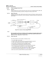
Страница 149: ...180 unit OFF 2 Plug the unit into the meter and the meter into the tested AC wall outlet 3 Plug the black chassis cable into the meter s CHASSIS connector and attach the black chassis cable clamp to an exposed metal part of the LOGIQ 180 unit 4 Set the meter s FUNCTION switch to the RESISTANCE position 5 Set the meter s POLARITY switch to the OFF center position 6 Measure and record the ground wir...

Страница 150: ...current When using the Microguard or a similar test instrument its power plug may be inserted into the wall outlet and the equipment under test is plugged into the receptacle on the panel of the meter This places the meter in the grounding conductor and the current flowing from the case to ground will be indicated in any of the current ranges The maximum allowable limit for chassis source leakage ...

Страница 151: ...hapter 10 Quality Assurance 10 15 8 Keep a record of the results with other hard copies of PM data kept on site 3 Mounting screw for peripheral plugged into unit 4 Mounting screw for other peripheral powered by unit Table 10 47 Chassis Leakage Current Test Condition TEST CONDITION ...

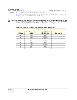
Страница 152: ...value shown in Table 10 44 Record all data on the PM Inspection Certificate Table 10 48 Typical Data Sheet for Chassis Source Leakage Current Unit Power Tester Polarity Switch Tester Neutral or Ground Switch Test 1 Probe Connector Screw Test 2 Rear Panel Optional Test 4 Optional Test 5 Enter Name of tested peripheral here ON NORM OPEN ON NORM CLOSED ON REV OPEN ON REV CLOSED OFF NORM OPEN OFF NORM...

Страница 153: ...sult from differences in line voltage and test lead placement 10 7 6 3 General procedure Follow these steps to test each transducer for leakage current 1 Turn the LOGIQ 180 unit OFF 2 Plug the unit into the test meter and the meter into the tested AC wall outlet 3 Plug the external probe into the meter s EXTERNAL connector 4 Set the meter s FUNCTION switch to EXTERNAL position 5 Connect the probe ...

Страница 154: ...N Equipment damage possibility Never switch the Polarity and the status of Neutral when the unit is powered ON Be sure to turn the unit power OFF before switching them using the POLARITY switch and or the NEUTRAL switch Otherwise the unit may be damaged Table 10 49 Typical Data Sheet For Transducer Source Leakage Current Transducer Tested Unit Power Tester Power Polarity Switch Tester GROUND or NU...

Страница 155: ...isolate if the fault lies with the probe or the scanner NOTE Each probe will have some amount of leakage dependent on its design Small variations in probe leakage currents are normal from probe to probe Other variations will result from differences in line voltage and test lead placement The maximum allowable leakage current for body surface contact probe differs from inter cavity probe Be sure to...

Страница 156: ...del Number Serial Number Manufacture Date Probe 1 Frequency Scan Format Model Number Serial Number Probe 2 Frequency Scan Format Model Number Serial Number Probe 3 Frequency Scan Format Model Number Serial Number Probe 4 Frequency Scan Format Model Number Serial Number Probe 5 Frequency Scan Format Model Number Serial Number Probe 6 Frequency Scan Format Model Number Serial Number Probe 7 Frequenc...

Страница 157: ...ured OK Comments Outlet correct ground wiring config System Ground Continuity Chassis Source Leakage Current Probe Patient Lead Source Leakage Lead to Ground Patient Lead Source Leakage Lead to Lead Patient Lead Source Leakage Isolation Peripheral 1 Leakage Current Peripheral 1Ground Continuity Peripheral 2 Leakage Current Peripheral 2Ground Continuity Peripheral 3 Leakage Current Peripheral 3Grou...

Страница 158: ...GE MEDICAL SYSTEMS DIRECTION 2317229 REVISION 3 LOGIQ 180 BASIC SERVICE MANUAL 10 22 Section 10 8 When There s Too Much Leakage Current This page was intentionally left blank ...

Страница 159: ...ing 2 2 M Manpower Requirements 2 4 Mechanical Safety 1 8 Models Covered 1 2 O Operating Temperature 2 1 P Physical Dimensions 3 18 Power Requirements 2 2 Power up Procedures Voltage Settings 3 9 Pre Installation 2 1 Prepearing the Unit for Installation 3 9 Probe Connector Cleaning 10 8 R Receiving and Unpacking the Equipment 3 4 S Safety Considerations 1 7 Site Circuit Breaker 2 2 Site Power Outl...

Страница 160: ...GE MEDICAL SYSTEMS DIRECTION 2317229 REVISION 3 LOGIQ 180 BASIC SERVICE MANUAL 2 Index ...

Страница 161: ......

Страница 162: ... Systems Telex 3797371 P O Box 414 Milwaukee Wisconsin 53201 U S A Asia Pacific Latin America North America GE Ultraschall Tel 49 0 212 28 02 208 Deutschland GmbH Co KG Beethovenstrabe 239 Postfach 11 05 60 D 42655 Solingen German ...

Отзывы: