CHAPTER 3: Replacing notebook components
90
5
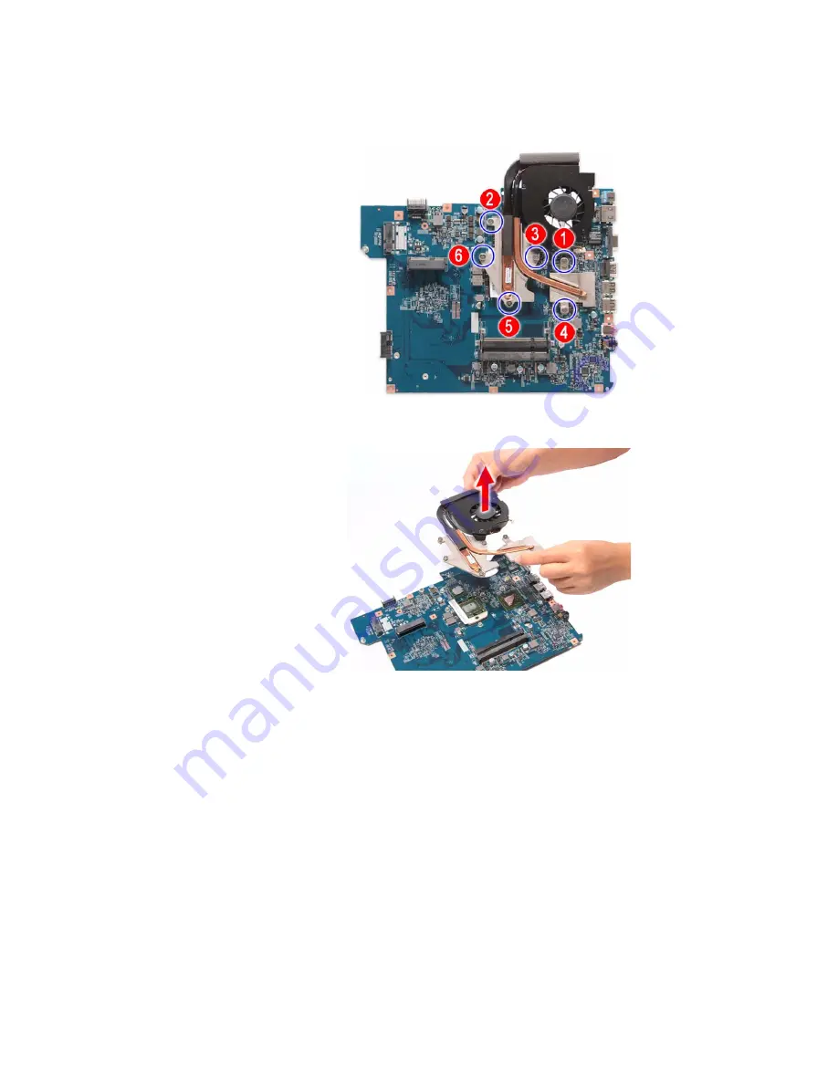
Loosen the spring-loaded captive screws securing cooling assembly.
Follow the screw sequence indicated on the below images.
6
Remove the cooling assembly from the system board.
7
Lay the cooling assembly down in an upright position to avoid tainting your
work space with thermal grease.
Содержание NV-53
Страница 1: ... NV53 SERVICEGUIDE ...
Страница 6: ...Contents iv ...
Страница 12: ...CHAPTER 1 System specifications 6 System block diagram ...
Страница 48: ...CHAPTER 2 System utilities 42 ...
Страница 140: ...CHAPTER 4 Troubleshooting 134 ...
Страница 141: ...CHAPTER5 135 Connector locations System board layout ...
Страница 144: ...CHAPTER 5 Connector locations 138 ...
Страница 145: ...CHAPTER6 139 FRU Field Replaceable Unit list Introduction Exploded diagram FRU list ...
Страница 157: ...APPENDIXA 151 Test compatible components Introduction Microsoft Windows Vista Environment Test ...
Страница 161: ...APPENDIXB 155 Online support information ...
Страница 167: ......
Страница 168: ...MAN NV5x SVC GDE R1 04 09 ...


