CHAPTER 1: System specifications
24
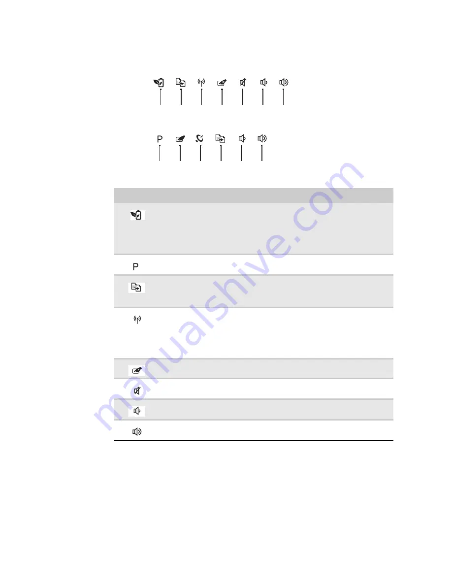
Using the capacitive touch keys
Button
Description
PowerSave key—enable Gateway PowerSave solution. The Gateway PowerSave
solution uses the power-saving features of your computer’s graphics sub-system
to reduce overall power consumption. When you press the Gateway PowerSave
key, the Windows graphics scheme will be changed to Windows Vista Basic, screen
brightness reduced and the graphics chip will be switched to a lower speed.
Press the Gateway PowerSave key again to return to your previous settings. (only
for certain models)
Programmable key—the programmable key will run the Launch Manager, you can
assign an application as your needed. (only for certain models)
MyBackup key—launch Gateway MyBackup solution. The Gateway MyBackup
solution is a simple three-step process that allows you to create backup copies of
your entire system or selected files and folders according to a schedule or as you
need to.
Wireless switch—turn the optional IEEE 802.11 wireless network radio on or off.
For more information, see “Wireless Ethernet Networking” in your online
User
Guide
.
Warning: Radio frequency wireless communication can interfere with equipment
on commercial aircraft. Current aviation regulations require wireless devices to be
turned off while traveling in an airplane. IEEE 802.11 communication devices are
examples of devices that provide wireless communication.
Touchpad toggle—turn the internal touchpad on and off.
Mute—mutes the sound. Press again to restore the sound.
Decrease volume
—press to decrease volume.
Increase volume
—press to increase volume.
PowerSave
Touchpad
toggle
Wireless
switch
Decrease
volume
Increase
volume
Mute
(only for certain models)
MyBackup
Programmable
key
Touchpad
toggle
Wireless
switch
Decrease
volume
Increase
volume
Mute
(only for certain models)
MyBackup
Содержание NV-53
Страница 1: ... NV53 SERVICEGUIDE ...
Страница 6: ...Contents iv ...
Страница 12: ...CHAPTER 1 System specifications 6 System block diagram ...
Страница 48: ...CHAPTER 2 System utilities 42 ...
Страница 140: ...CHAPTER 4 Troubleshooting 134 ...
Страница 141: ...CHAPTER5 135 Connector locations System board layout ...
Страница 144: ...CHAPTER 5 Connector locations 138 ...
Страница 145: ...CHAPTER6 139 FRU Field Replaceable Unit list Introduction Exploded diagram FRU list ...
Страница 157: ...APPENDIXA 151 Test compatible components Introduction Microsoft Windows Vista Environment Test ...
Страница 161: ...APPENDIXB 155 Online support information ...
Страница 167: ......
Страница 168: ...MAN NV5x SVC GDE R1 04 09 ...


