Components 9
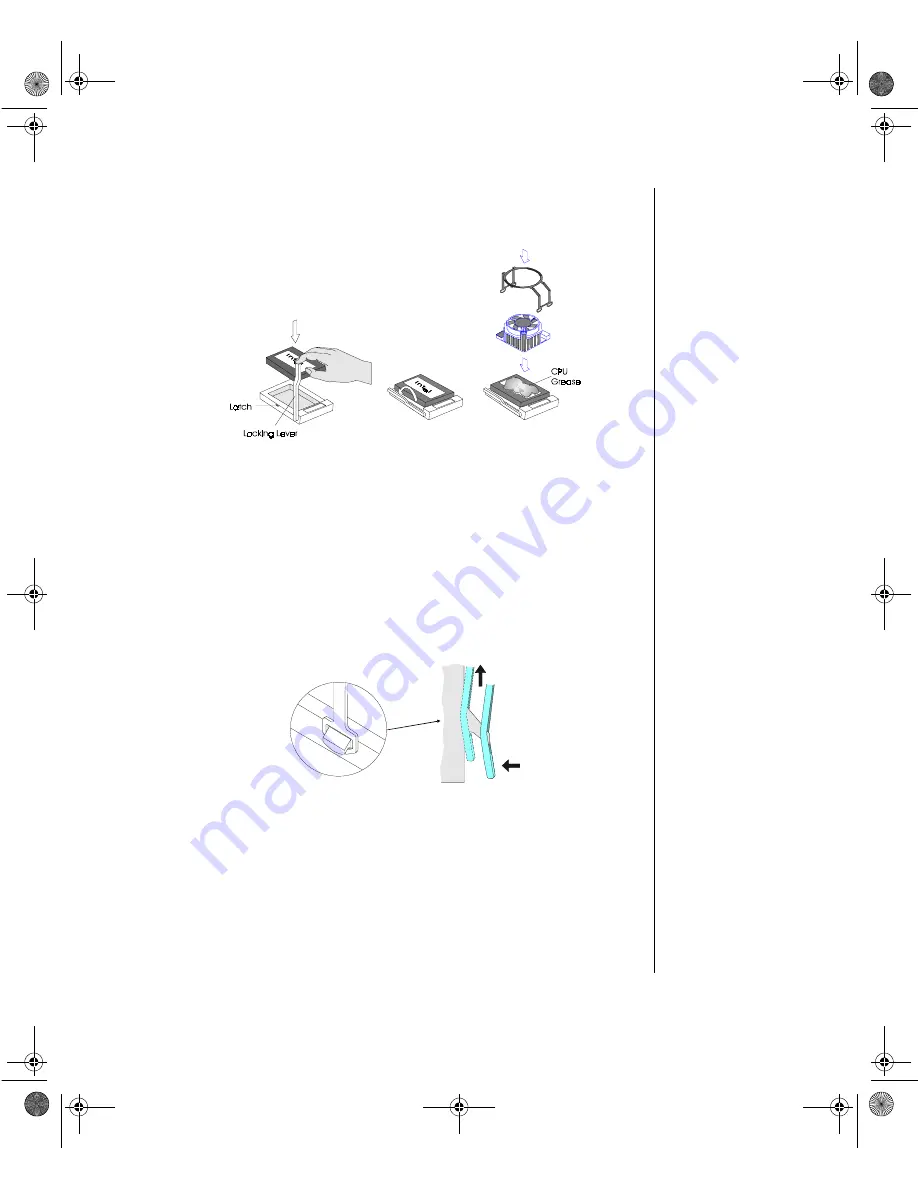
6. Gently swing the locking lever away from the CPU socket and lift it up.
Refer to Figure 6.
7. Carefully place the CPU into the socket and secure it by lowering the locking
lever until the lever latches into place.
8. Apply a layer of CPU grease to the top of the CPU to ensure proper contact
and heat dissipation.
9. Place the fansink assembly squarely on top of the CPU.
10. Secure the assembly by clipping the bracket to the plastic flanges on the CPU
socket as shown in Figure 7.
11. Repeat steps 6 thru 10 for additional CPUs (maximum six CPUs, three per
CPU card).
Figure 6: Installing a CPU
Figure 7: Installing the CPU Clip
Maints.boo Page 9 Friday, July 10, 1998 1:47 PM
Содержание ALR 9000
Страница 10: ...x Maintaining and Troubleshooting the Gateway ALR 9000 Server Maints boo Page x Friday July 10 1998 1 47 PM...
Страница 14: ...xiv Maintaining and Troubleshooting the Gateway ALR 9000 Server Maints boo Page xiv Friday July 10 1998 1 47 PM...
Страница 21: ...Components 7 Figure 3 CPU Installation Guide Maints boo Page 7 Friday July 10 1998 1 47 PM...
Страница 29: ...Components 15 Figure 14 Installing Memory Units Maints boo Page 15 Friday July 10 1998 1 47 PM...
Страница 38: ...24 Maintaining and Troubleshooting the Gateway ALR 9000 Server Maints boo Page 24 Friday July 10 1998 1 47 PM...
Страница 54: ...40 Maintaining and Troubleshooting the Gateway ALR 9000 Server Maints boo Page 40 Friday July 10 1998 1 47 PM...
Страница 62: ...48 Maintaining and Troubleshooting the Gateway ALR 9000 Server Maints boo Page 48 Friday July 10 1998 1 47 PM...


