50
Replacing and Adding System Components
15
Reinstall the back access panel following the instructions on page 23.
16
Reconnect peripherals, the modem cord, and the power cord, then turn
on the system.
17
You must enable Processor Retest from the BIOS Setup utility whenever
you replace or add a processor.
To add an additional processor:
1
Observe the safety and ESD precautions in “Preventing static electricity
discharge” on page 15.
2
Turn off the system and disconnect the power cord(s), modem cord (if
installed) and all other external peripheral devices.
3
Remove the back access panel. (See “Removing the side panels” on
page 18.)
4
Loosen the captive screw securing the memory module retention bracket
to the chassis, then swing the retention bracket out from the chassis.
5
Remove the foam cover from the lower electronics bay. (Do not remove
the plastic air baffle attached to the foam cover.)
6
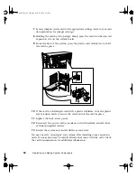
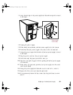
Using a Phillips screwdriver, remove the screws holding the retention
bracket to the processor retention module of the next processor slot.
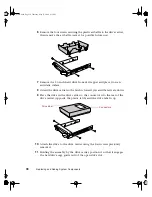
Retention bracket
Termination
board
Retention module
05895.book Page 50 Thursday, May 11, 2000 1:11 PM
Содержание 8400
Страница 1: ...8400 Server System Manual A MAN US 8400 SYS GDE R0 5 00 ...
Страница 5: ...iv 05895 book Page iv Thursday May 11 2000 1 11 PM ...
Страница 9: ...viii 05895 book Page viii Thursday May 11 2000 1 11 PM ...
Страница 87: ...78 Using the BIOS Setup Utility 05895 book Page 78 Thursday May 11 2000 1 11 PM ...
Страница 121: ...112 Troubleshooting 05895 book Page 112 Thursday May 11 2000 1 11 PM ...
Страница 137: ...128 Safety and Regulatory Information 05895 book Page 128 Thursday May 11 2000 1 11 PM ...
Страница 146: ...8400 Server System Manual A MAN US 8400 SYS GDE R0 5 00 ...


