34
Replacing and Adding System Components
8
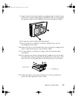
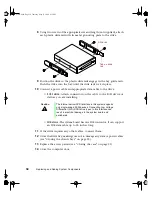
Using two screws of the appropriate size and length (not supplied), attach
each plastic slide rail with its metal grounding plate to the drive.
9
Position the drive so the plastic slide rails engage in the bay guide rails.
Push the drive into the bay until the slide rails lock in place.
10
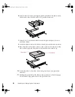
Connect a power cable and appropriate data cable to the drive.
■
SCSI drive:
Attach connectors on the cable to the SCSI device or
devices you are installing.
■
IDE drive:
The system board has one IDE connector. It can support
an IDE data cable up to 18 inches long.
11
If the drive requires any other cables, connect them.
12
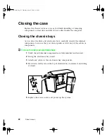
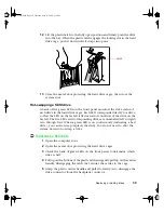
Close the drive bay, making sure not to damage any data or power cables
(see “Closing the chassis bays” on page 22).
13
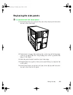
Replace the access panels (see “Closing the case” on page 22).
14
Close the computer door.
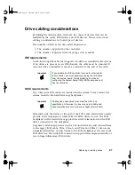
Caution
The internal narrow SCSI interface in this system supports
only single-ended SCSI devices. Connecting Low Voltage
Differential (LVD) SCSI drive types to this interface can
result in electrical damage to the system board and
peripherals.
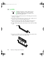
Slide rail
Tab on slide
rail
05895.book Page 34 Thursday, May 11, 2000 1:11 PM
Содержание 8400
Страница 1: ...8400 Server System Manual A MAN US 8400 SYS GDE R0 5 00 ...
Страница 5: ...iv 05895 book Page iv Thursday May 11 2000 1 11 PM ...
Страница 9: ...viii 05895 book Page viii Thursday May 11 2000 1 11 PM ...
Страница 87: ...78 Using the BIOS Setup Utility 05895 book Page 78 Thursday May 11 2000 1 11 PM ...
Страница 121: ...112 Troubleshooting 05895 book Page 112 Thursday May 11 2000 1 11 PM ...
Страница 137: ...128 Safety and Regulatory Information 05895 book Page 128 Thursday May 11 2000 1 11 PM ...
Страница 146: ...8400 Server System Manual A MAN US 8400 SYS GDE R0 5 00 ...


