


10.
Initial status and Menu description
10.1.
Initial operation status (Power On)
After wiring of and power supplying to Power Terminal on MAIN PCB board, the following information
will be displayed on the LCD display. About 30 minutes of stabilization time is required about 30
minutes’ stabilization time is required; normal operation begins after full stabilization.
After the Power ON, the model name and product firmware Revision
number is displayed on
LCD (OLED).
Self test runs for one minute, and the '>' character in second row
indicates the progress.
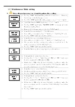
10.2.
Gas measuring status (Measuring Mode) configuration
Operation is as follows in Normal state.
In the first row, Measuring GAS NAME and Measuring GAS Unit are displayed
alternately every second; in the second row, current Measuring Value is displayed.
Touching ‘Func’ Key with Magnet-bar for 2 seconds in current screen will change to
Setting Mode.
※
During HART communications, '*' character is displayed on the left side of
the 1
st
row.
※
When ENG. Mode is ON, '<' character is marked on the left side of the 2nd
row.
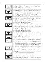
The operation is as follows when 1
st
or 2
nd
Alarm has occurred (ALARM EN item of
Maintenacne Mode must be ON to enable the operation).
The 1
st
row is operated the same as in Normal mode; in the 2
nd
row, ALARM
messages and Gas Measuring Value are displayed alternately every 1 second.
When GTL100 Explosion-proof Warning Light is installed, the red LED and Buzzer
are blinking every second in the 1
st
Alarm; no flashing occurrs in the 2nd Alarm.
Alarm condition continues unless it was released using Reset key if the Latch is on
during Alarm function.
If the entered Gas Measuring Valueis more than 10% higher than set High
Scale, the word “OVER” is displayed blinking every 1 second.
At this time 4~20mA is operated as 21.6mA.
If the entered Gas Measuring Valueis less than 10% lower, the word “UNDER” is
displayed blinking every 1 second; 4 ~ 20mA is operated below 2mA.
※
This feature is operated only when UNDER button is ON.
If there is any problem with the device, the Fault number and message will
be displayed.
At this time, the 4 ~ 20mA is operated below 2mA.
The left Mode is displayed when Fault1 sensor is not equipped.
[FAULT1]
[FAULT1]
[FAULT1]
[FAULT1]
SEN EMPT
SEN EMPT
SEN EMPT
SEN EMPT
[ %LEL]
[ %LEL]
[ %LEL]
[ %LEL]
[ UNDER ]
[ UNDER ]
[ UNDER ]
[ UNDER ]
[ %LEL]
[ %LEL]
[ %LEL]
[ %LEL]
[ OVER ]
[ OVER ]
[ OVER ]
[ OVER ]
[ %LEL]
[ %LEL]
[ %LEL]
[ %LEL]
[[[[ A L A R M 1
A L A R M 1
A L A R M 1
A L A R M 1 ]]]]
[ %LEL]
[ %LEL]
[ %LEL]
[ %LEL]
[
[
[
[
[ COMB.]
[ COMB.]
[ COMB.]
[ COMB.]
[ 0.0]
[ 0.0]
[ 0.0]
[ 0.0]
[ %LEL]
[ %LEL]
[ %LEL]
[ %LEL]
[ 0.0]
[ 0.0]
[ 0.0]
[ 0.0]
SELF TEST
SELF TEST
SELF TEST
SELF TEST
[[[[ >>>>>>>>>>>
>>>>>>>
>>>>>>>
>>>>>>>]]]]
GTD
GTD
GTD
GTD----2000
2000
2000
2000
[ REV 6]
[ REV 6]
[ REV 6]
[ REV 6]


