190-00692-00 Rev. B
Garmin G1000 Pilot’s Guide for Piper PA32
1-35
SYSTEM OVERVIEW
A
UDIO
A
LERTS
The Audio Alert Box on the System Setup Page allows the audio alert voice to be set to male or female.
Changing the audio alert voice:
1)
While on the System Setup Page, press the
FMS
Knob momentarily to activate the flashing cursor.
2)
Turn the large
FMS
Knob to highlight the voice in the Audio Alert Box.
3)
Turn the small
FMS
Knob to display and highlight the desired voice and press the
ENT
Key.
MFD D
ATA
B
AR
F
IELDS
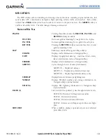
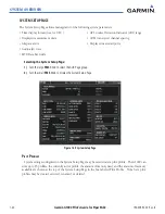
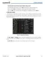
The MFD Data Bar Fields Box on the System Setup Page displays the current configuration of the MFD
Navigation Status Box. By default, the Navigation Status Bar is set to display ground speed (GS), distance
to next waypoint (DIS), estimated time en route (ETE), and en route safe altitude (ESA).
Changing the information shown in an MFD Navigation Status Bar field:
1)
While on the System Setup Page, press the
FMS
Knob momentarily to activate the flashing cursor.
2)
Turn the large
FMS
Knob to highlight the desired field number in the MFD Data Bar Fields Box.
3)
Turn the small
FMS
Knob to display and scroll through the data options list and press the
ENT
Key when the
desired data selection is highlighted.
The following data may be selected for display in each of the four fields of the Navigation Status Box.
• Bearing (BRG)
• Distance (DIS)
• Desired Track (DTK)
• En Route Safe Altitude (ESA)
• Estimated Time of Arrival (ETA)
• Estimated Time En Route (ETE)
• Ground Speed (GS)
• Minimum Safe Altitude (MSA)
• True Air Speed (TAS)
• Track Angle Error (TKE)
• Track (TRK)
• Vertical Speed Required (VSR)
• Crosstrack Error (XTK)
GPS CDI
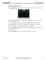
The GPS CDI Box on the System Setup Page allows the pilot to define the range for the on-screen course
deviation indicator (CDI). The range values represent full range deflection for the CDI to either side. The
default setting is ‘AUTO’. At this setting, leaving the departure airport the CDI range is set to 1.0 nm and
gradually ramps up to 2.0 nm beyond 30 nm from the departure airport. The CDI range is set to 2.0
nautical miles during the en route phase of flight. Within 31 nm of the destination airport, the CDI range
gradually ramps down to 1.0 nm (terminal area). During approach operations, the CDI range ramps down
even further to 0.3 nm, or less using angular scaling. This transition normally occurs within 2.0 nm of the
final approach fix (FAF) and the desired track is within 45 degrees of the IAF to FAF segment.
Содержание G1000:Piper
Страница 1: ...Piper PA32...
Страница 50: ...190 00692 00 Rev B Garmin G1000 Pilot s Guide for Piper PA32 1 40 SYSTEM OVERVIEW BLANK PAGE...
Страница 80: ...Garmin G1000 Pilot s Guide for Piper PA32 190 00692 00 Rev B 2 30 FLIGHT INSTRUMENTS BLANK PAGE...
Страница 94: ...Garmin G1000 Pilot s Guide for Piper PA32 190 00692 00 Rev B 3 14 ENGINE INDICATION SYSTEM BLANK PAGE...
Страница 134: ...190 00692 00 Rev B Garmin G1000 Pilot s Guide for Piper PA32 4 40 AUDIO PANEL AND CNS BLANK PAGE...
Страница 249: ...GPS NAVIGATION 190 00692 00 Rev B 5 115 Garmin G1000 Pilot s Guide for Piper PA32 Figure 5 121 Approaching PYNON...
Страница 254: ...GPS NAVIGATION 190 00692 00 Rev B 5 120 Garmin G1000 Pilot s Guide for Piper PA32 Figure 5 129 Hold Established...
Страница 352: ...Garmin G1000 Pilot s Guide for Piper PA32 190 00692 00 Rev B 7 2 AUTOMATIC FLIGHT CONTROL SYSTEM BLANK PAGE...
Страница 438: ...190 00692 00 Rev B Garmin G1000 Pilot s Guide for Piper PA32 D 6 APPENDIX D BLANK PAGE...
Страница 444: ...190 00692 00 Rev B Garmin G1000 Pilot s Guide for Piper PA32 F 4 APPENDIX F BLANK PAGE...
Страница 450: ...Garmin G1000 Pilot s Guide for Piper PA32 190 00692 00 Rev B I 6 INDEX BLANK PAGE...

