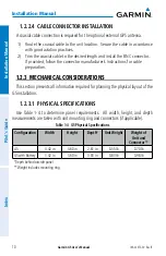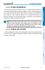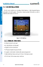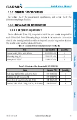
Garmin G5 User's Manual
190-02072-00 Rev. B
8
Installation Manual
Installation Manual
Pilot's Guide
Index
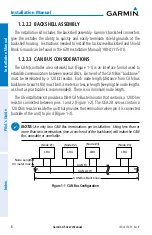
1.2.2.2 BACKSHELL ASSEMBLY
The installation kit includes the backshell assembly. Garmin’s backshell connectors
give the installer the ability to quickly and easily terminate shield grounds at the
backshell housing. Instructions needed to install the Jackscrew Backshell and Shield
Block Ground can be found in the G3X Installation Manual (190-01115-01).
1.2.2.3 CAN BUS CONSIDERATIONS
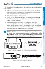
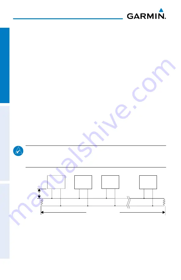
The CAN (controller area network) bus (Figure 1-1) is an interface format used to
establish communication between several LRUs. Each end of the CAN Bus “backbone”
must be terminated by a 120
Ω
resistor. Each node length (distance from CAN bus
backbone to each LRU) must be 0.3 meters or less in length (keeping the node lengths
as short as practicable is recommended). There is no minimum node length.
The G5 installation kit provides a DB-9 CAN Bus terminator that contains a 120 Ohm
resistor connected between pins 1 and 2 (Figure 1-2). The GSA 28 servos contain a
120 Ohm resistor inside the unit that provides the termination when pin 3 is connected
(outside of the unit) to pin 4 (Figure 1-3).
NOTE:
Use only two CAN Bus terminations per installation. Using less than or
more than two terminations (one at each end of the backbone) will make the CAN
Bus unusable or unreliable.
R
L
R
L
CAN Bus Backbone
CAN HI
CAN LOW
(Node #1)
LRU
(Node #2)
LRU
(Node #3)
LRU
(Node #n)
LRU
Node Length
0.3 meter max.
Figure 1-1 CAN Bus Configuration
Содержание Approach G5 - GPS-Enabled Golf Handheld
Страница 1: ...G5 User s Manual...
Страница 2: ...INSTALLATION MANUAL PILOT S GUIDE INDEX...
Страница 100: ...Garmin G5 User s Manual 190 02072 00 Rev B 88 Installation Manual Installation Manual Pilot s Guide Index Blank Page...
Страница 167: ...Garmin G5 User s Manual 190 02072 00 Rev B Blank Page...

