background image

- 6 -

1

2

3

4

5

6

7

8

9

10 11 12 13 14 15 16 17 18 19 20 21 22 23 24 25 26

X 1

4

O

4.2 Electrical installation

4.2.1 General

Compare the electrical data of the motor and control system with available mains supply (type of current, voltage, supply frequency,
permitted amperage)  (see data plate (N) in D 140 and D 141). Connect pumps via a motor starter to protect the motor, and
standards relating to strain relief of the connecting cable should be complied with.
We recommend the use of motor starter with thermal and magnetic overload protection.  A temporary overload may occur during
a cold start.

The electrical installation may only be made by a qualified electrician under the observance of EN 60204. The main
switch must be planned through the operator.

The approximate values for setting motor overload protection should be obtained from the motor manufacturer or motor
nameplate.

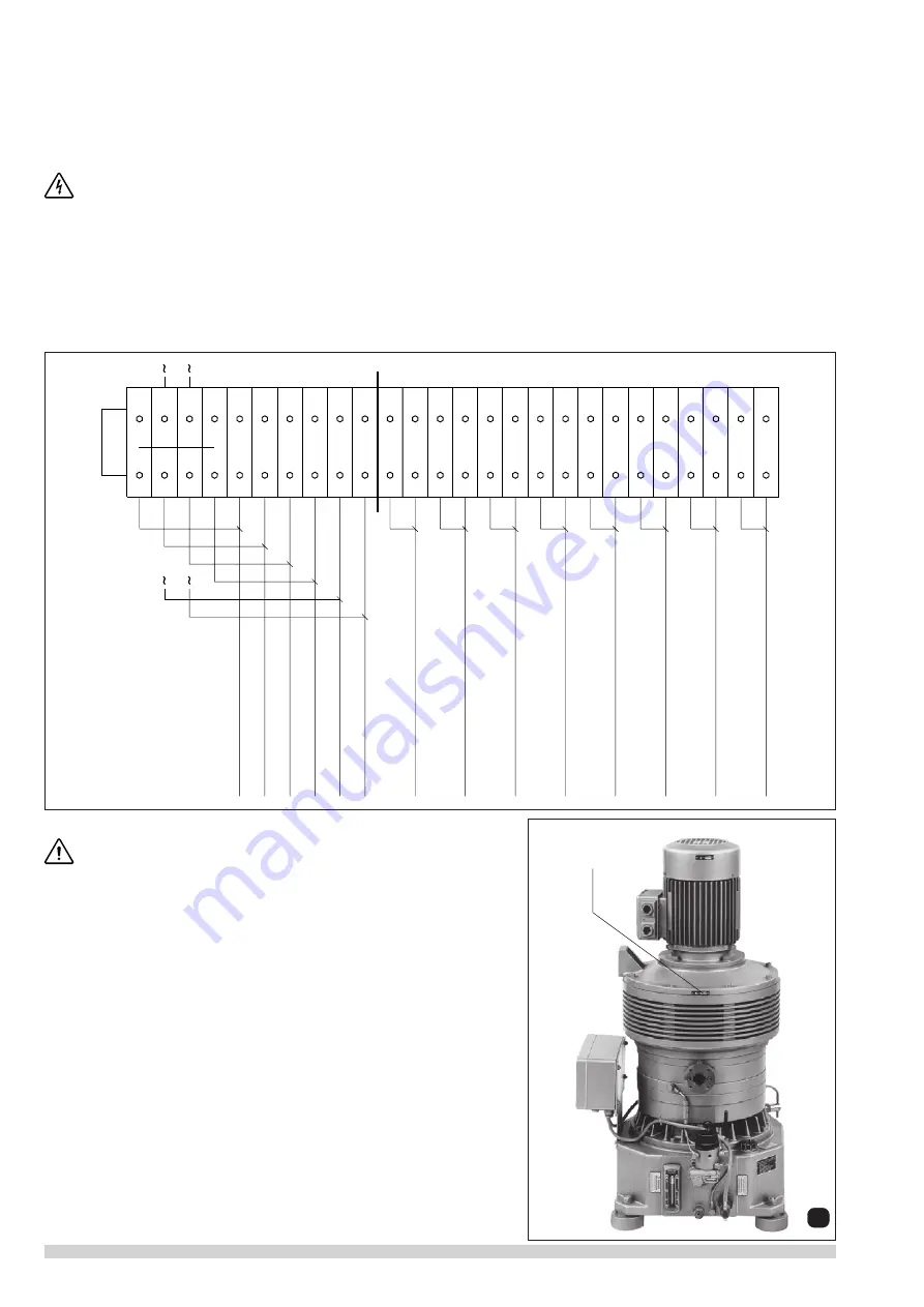
4.2.2 Electrical connections for motor and control of monitoring systems

All electrical connections for the motor and for the control of the monitoring systems are housed in terminal boxes.  Each  conductor
terminal is numbered, and all connections for motor and monitoring elements are allocated a specific number (see circuit diagram).
Connection numbers must be observed during refitting or repair work to simplify detection  of causes of faults.

4.2.3 Terminal box Connections

Suction valve

Bleeding valve

V

alve flushing unit

V

alve fr

esh oil

V

alve oil mist separator

Reserve

Reserve

Reserve

Level pr

e-separator

Level flushing liquid

Reserve

Level oil mist separator

Level fr

esh oil VL

V

Level fr

esh oil flushing

4.3 Initial Operation

Warning –> Start-up with pipework

At start-up, severe damage may occur if there is debris in the pipework.
We therefore recommend a vacuum tight inlet filter of 5 micron rating is
installed for start-up.

Start the pump briefly to check the direction of rotation (see arrow (

O

)).

Warning.

  When handling moist and aggressive media, the vacuum pump

must be operated against the closed suction side but open bleed valve
(accessory) before and after the process.  Pre-run and post-run last about 20
to 30 minutes.  The pump is brought to operating temperature during the pre-
run to prevent condensation of moist media inside the pump. Residues are
flushed out by the post-run and are purged before stoppage. Pre-run and post-
run take place automatically when the selector switch is set accordingly.

Содержание Elmo Rietschle VLV Series

Страница 1: ...80 2 VLV 80 3 VLV 100 2 VLV 100 3 Gardner Denver Schopfheim GmbH Postfach 1260 79642 SCHOPFHEIM GERMANY Fon 49 7622 392 0 Fax 49 7622 392 300 e mail er de gardnerdenver com www gd elmorietschle com B...

Страница 2: ...uumpumpen VLV 5 3 2 14 Einsatzgrenzen VLV 5 4 Installation und Inbetriebnahme 5 4 1 Mechanische Installation 5 4 1 1 Aufstellung 5 4 1 2 Saugseite 5 4 1 3 Abluftseite 5 4 2 Elektrische Installation 6...

Страница 3: ...len oder ein Ausfall derVakuumpumpezueinerGef hrdung vonPersonenoderEinrichtungenf hrt sind entsprechende Sicherheitsma nahmen anlagenseits vorzusehen 3 Ausf hrungen und Aufbau 3 1 Ausf hrungen Die Ty...

Страница 4: ...er 3 bzw 2 Stufen und das obere Rotorlager mit Frisch l versorgt Die lschmierpumpe hat 4 Schmierstellen bei der VLV 2 bzw 6 Schmierstellen bei der VLV 3 Bei der Lagerschmierung flie t das l vom oberen...

Страница 5: ...Dauer f r den Vor und Nachlauf liegt bei ca 20 30 Minuten Ausreichende K hlm glichkeit der Pumpe mu vorhanden sein siehe 4 1 1 Aufstellung berpr fen ob die Umgebungsluft stark aggressiv ist da evtl A...

Страница 6: ...f r Motor und f r die Steuerung der Kontroll Einrichtungen befinden sich im Klemmenkasten Jede Anschlu klemme der Klemmenleiter hat eine Nummer und alle Anschl sse f r Motor und Kontroll Organe sind...

Страница 7: ...ge Weniger l Mehr l lschmierpumpe VLV 25 2 25 3 40 2 40 3 60 2 60 3 80 2 80 3 100 2 100 3 50 Hz 0 065 0 097 0 065 0 097 0 065 0 195 0 065 0 195 0 065 0 195 60 Hz 0 078 0 117 0 078 0 117 0 078 0 234 0...

Страница 8: ...t bersteigen Wird das Endvakuum nicht erreicht folgende Arbeiten durchf hren Sieb im Saugflansch ausbauen und reinigen berstr mventile ausbauen auf Funktion berpr fen Vakuum zwischen ND MD und HD Stuf...

Страница 9: ...0 2 VLV 80 3 VLV 100 2 VLV 100 3 Gardner Denver Schopfheim GmbH Postfach 1260 79642 SCHOPFHEIM GERMANY Fon 49 7622 392 0 Fax 49 7622 392 300 e mail er de gardnerdenver com www gd elmorietschle com Vac...

Страница 10: ...y 5 4 Installation and commissioning 5 4 1 Mechanical installation 5 4 1 1 Installation 5 4 1 2 Suction side 5 4 1 3 Exhaust 5 4 2 Electrical installation 6 4 2 1 General 6 4 2 2 Electrical connection...

Страница 11: ...planned shut down of the pump could possibly cause harm to persons or installations then the corresponding safety backup system must be installed 3 Design and Construction 3 1 Models The VLV range is...

Страница 12: ...ntainer the oil passes through an overflow orifice back into the fresh oil reservoir 3 2 5 Oil separation The oil containing exhaust flows from the HP stage into the used oil and condensate reservoir...

Страница 13: ...cations Vacuum for printed circuit board production Carbonisation in drink production Vacuum packaging of moist products Vacuum cooling of foods Vacuum filtration Vacuum drying Vacuum crystallisation...

Страница 14: ...numbered and all connections for motor and monitoring elements are allocated a specific number see circuit diagram Connection numbers must be observed during refitting or repair work to simplify detec...

Страница 15: ...tion for VLV l hr Oil Consumption for VLV Roots booster on request VLV 25 2 25 3 40 2 40 3 60 2 60 3 80 2 80 3 100 2 100 3 50 Hz 0 065 0 097 0 065 0 097 0 065 0 195 0 065 0 195 0 065 0 195 60 Hz 0 078...

Страница 16: ...the instruction manual c Maintenance during Storage The pumps should be operated once a month for about 2 hours to prevent any kind of corrosion within the pump Please pay attention to the fact that t...

Отзывы: