- 3 -
1
1. Introduction
In the event of a pump being re-
turned to us, for whatever reason
(eg.repair) it must be free of all danger-
ous and toxic material. A corrosponding
certificate has to be presented!
Explosion proof standards for the plant in
which the vacuum pump will be installed,
are the responsibility of the customer and
should have the approval of the appropri-
ate factory inspectorate..
2. Applications
VLV vacuum pumps are available for han-
dling a wide range of gases including
those which are extremely moist or ag-
gressive. They can also handle large quan-
tities of water vapour.
The ambient and suction tempera-
tures may be between 5 and 40° C.
For temperatures out of this range please
contact your supplier.
Suitable equipment should be fitted to
prevent slugs of liquid or solid parti-
cles being drawn into the pump.
Handling of explodible gases or va-
pours only on request with our com-
pany.
The standard versions may not be han-
dled in explosion areas. Special Ex-proof
versions can be supplied.
For installations that are higher
than 1000 m above sea level there
will be a loss in capacity. For further
advice please contact your supplier.
All applications where an unplanned
shut down of the pump could possibly
cause harm to persons or installations,
then the corresponding safety backup
system must be installed.
3. Design and Construction
3.1 Models
The VLV range is available in 5 capacities: 25, 40, 60, 80 and 100 m³/hr
These, in turn, are available in 2-stage and 3-stage versions. 2-stage vacuum pumps reach an ultimate vacuum of 0.5mbar, and
3-stage vacuum pumps 0.02 mbar. Cooling is by a centrifugal fan, between motor and last compressor stage, which draws the
cooling air through air ducts in the compressor units.
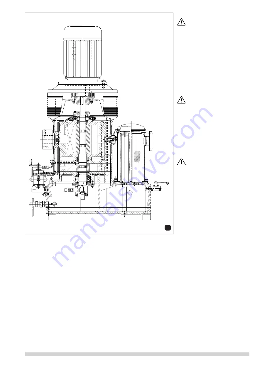
3.2 Construction of 2- and 3-stage VLV
3.2.1 General construction details
VLV machines are 2- or 3- stage vacuum pumps featuring fresh oil lubrication.
The individual stages are stacked, the rotor shaft being vertical.
The drive motor is situated at the top, above a centrifugal fan which is followed by the LP-stage, MP-stage and HP-stage. The
MP-stage is omitted from 2-stage versions.
The entire base unit stands on a combined fresh oil and condensate/used oil reservoir.
A by-pass valve is fitted between LP- and HP-stage, and also between MP- and HP-stage in the 3-stage model, to prevent over-
compression at low vacuum (from VLV-40 capacity only).
Condensate discharge channels are provided in the bottom of the compression chambers. Condensate can therefore flow out even
when the pump is not running.
Cut view VLV-2


