G
AMATRONIC
E
LECTRONIC
I
NDUSTRIES
L
TD
.
MegaV2 250 Installation Guide, Release 2.2
32
5
.
Turn off the input and output circuit breakers on the rear panel of the module to be
removed.
6
.
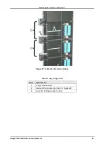
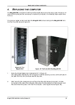
Disconnect the flat cable (module communication cable) from the right side of the module (see
Figure 28). If the LCD screen happens to be connected to the module to be removed, you must
also disconnect the LCD communication cable from the right side of the screen, and
remove the LCD screen itself to avoid accidental damage to it.
7
.
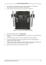
Unscrew the two screws that secure the module – one on the left side, one on the right side
(see item 2 in Figure 26 on page 28).
8
.
Push down simultaneously on the levers on the left and right side of the module. This
pushes the module out from the UPS frame a little.
9
.
Two persons are required to remove the module. Let one person stand on the left side of
the module, the other on the right side of the module. Slowly pull the module out of the
shelf.
Be prepared for the fact that when the module is pulled out about 15 cm its
weight will no longer be supported by the shelf
and will be fully in the hands of the two
workers. (Before you take the module out of the shelf, have a place where to lay it down
after it is removed.)
10
.
Slide the replacement module into place. Push it all the way in and then push up
simultaneously on the two levers, one on each side of the module.
11
.
Secure the module with one screw on each side (see item 2 in Figure 26 on page 28).
12
.
Connect the flat cable (module communication cable) to the right side of the module
(Figure 28).
13
.
If the LCD screen is to be connected to the replacement module, attach it to the module
now, then attach the LCD power/communication cable to the LCD screen and power-on the
screen. See section 3 on page 40 for instructions on how to install the LCD screen.
14
.
On the rear of the replacement module, switch "ON"
only the input
circuit breaker.
15.
Navigate to "Setup > System > Nominal Settings" and click the Confirm button. (This sends
the system's nominal values for voltage and frequency to the replacement module.)
16.
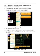
Navigate to "Status > Modules" and select the replacement module (the modules are
numbered from bottom to top). Then click the Nominals button near the bottom of the
screen, and verify that the values for output voltage, output frequency, and frequency range
match the system nominal settings.
17
.
Navigate to "Operation > Turn on/off > Modules on". Select the module to be switched "ON"
and press "Confirm". (You may be prompted for the system password.)
18
.
To verify that the module is operating normally, navigate to the module status screen
("Main screen > Status > Modules"), press on the icon of the module that was just
switched on, and verify that the status is "ON" for these five items: PFC, Inverter, Dc relay,
Input relay, Output relay. Verify that the other fields are also normal.

