G
AMATRONIC
E
LECTRONIC
I
NDUSTRIES
L
TD
.
MegaV2 250 Installation Guide, Release 2.2
5
1.2.3
Site Preparation – Electrical
Perform the following procedures before connecting any external cables to
MegaV2 250
.
1
.
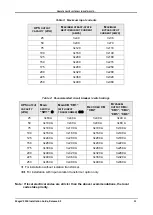
Read Chapter 5 “Circuit breaker selectivity” in this installation guide. That chapter includes
recommendations for the size of the circuit breakers on the rectifier input and bypass input
lines.
2.
Verify that circuit breakers on the electrical board that supplies
MegaV2 250
are compliant
with local and national codes and Gamatronic system specifications.
3.
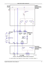
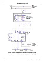
Verify that the input and output power cable connections, GND, and neutral lines comply
with local and national codes and are appropriate for the circuit breakers protecting them.
4.
Measure the ac input voltage. Phase-to-phase voltage (measured between L1-L2, L2-L3,
and L3-L1) should be 3x400 Vac ±10 %. Phase-to-neutral voltage (measured at L1, L2, and
L3) should be 230 Vac, ±10 %.
5.
Verify that voltage between neutral and ground is between 0 and +2 Vac.
6.
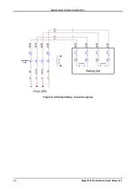
Check the dc voltage at the switch of the battery cable and verify that it is
+360 V and -360 V.
1.2.4
Cabling
1.2.4.1
Installing the cable guard
Before connecting the ac input and output lines and the battery lines to the UPS bus bars, the
cable guard must be installed. The cable guard is pictured in Figure 2 and Figure 3.
Bore holes in the rear external panel of the cable guard (item 3 in Figure 3) large enough to
enable the ac cables and the battery cables to pass through. Attach the cable guard's rear panel
(item 3 in Figure 3) to the cable guard (item 2 in Figure 3).
Figure 2: The cable guard (without and with its rear panel)
When attaching the ac and dc cables to the UPS (described in the following sections) the cables
must be threaded through the holes that you drilled in the cable guard rear panel.


