


4
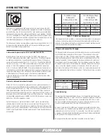
Source
120/208
Three Phase
120/240
Single Phase
Cable
Color
Black
Red
Blue, Brown, or Orange
Black
Red
Buss
Bar
X
Y
Z
X
Y
Circuits
A,D
B,E
C,F
A,C,E
B,D,F
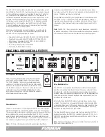
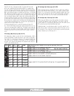
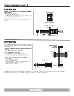
Table 2. Load Balancing Example
6. Next, terminate the source end of the cable:
The source end of the cable must be terminated by a qualified electrician
in accordance with national, local and municipal safety standards.
An example of how the loads should be connected is shown in Table 2.
To move a wire, grasp it by the terminal and pull straight up. Then re-position it
over an unused Fast-On male terminal on the appropriate bus bar and push down
firmly. Do not pull on the wires as this may compromise the integrity of the wire
crimp. If it is necessary to move load conductors, it will not be necessary to move
the smaller Phase LED indicator wires.
5. Tighten the cable strain relief clamp firmly:
At least one half inch of the outer jacket must extend beyond the clamp into the
interior of the unit. Replace the top cover. This completes the internal wiring of
the ASD-120 2.0.
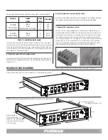
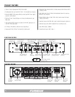
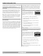
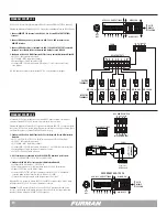
REAR RACK EAR MOUNTING
1.
Remove the screws from the side of the ASD-120 2.0 adjustable rear rack ear.
START
SEQUENCE
REMOTE
DLY
ADJ
DELAY A DELA
Y B
DELA
Y C
PHASE
X Y Z
DELAY D DELA
Y E
DELA
Y F
OFF ON
1 2 3 4 5 6 7
ALWAYS ON
ALWAYS OFF
ASD-120 2.0
120 AMP POWER SEQUENCER
(SEE COVER PLA
TE)
START
SEQUENCE
REMOTE
DLY
ADJ
DELAY A DELA
Y B
DELA
Y C
PHASE
X Y Z
DELAY D DELA
Y E
DELA
Y F
OFF ON
1 2 3 4 5 6 7
ALWAYS ON
ALWAYS OFF
ASD-120 2.0
120 AMP POWER SEQUENCER
(SEE COVER PLA
TE)
2.
Reverse the rack ears and reattach the rack ears to the chassis (as shown here).
3.
Adjust length to
connect to back side of
equipment rack. (Maximum
reach from the front to the rear
is 20.75 inches).
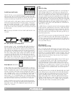
7. Optional 120V single phase source:
The ASD-120 2.0 can be powered from a 120VAC source, with the AC source
connected between the X and NEUT bus bar inputs, but the source current must
not exceed 60 amps and the maximum load must not exceed the source current.
The number of output circuits connected to the X bus bar must not exceed the
source current divided by 20A. For example, a 120 Volt 60 Amp feed will limit the
Furman ASD-120 2.0 to a capability of only (3) 20A breaker circuits, and there-
fore, only 3 internal load conductors are recommended. (Only three 20A circuits
will be operational and the other three 20A circuits must be defeated.)
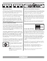
19 in.
17 in.
10 in. (allow an extra inch
for connectors, buttons, etc.)
3.5 in.
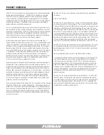
Internal power distribution block terminals (See torque specs on page 3).


