

15
LOCAL AND REMOTE OPERATING MODES
Other configuration options are possible with an understanding of the REMOTE in-
terface and configuration features of the ASD-120 2.0 discussed in the following
sections.
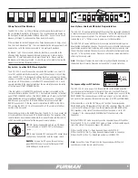
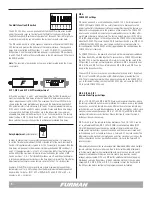
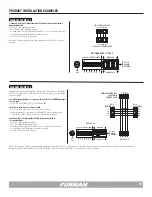
Key Switch Control
Secured local control of the ASD-120 2.0 is best accomplished by using the
front panel Key Switch. When in the ON position, all Delay Banks will sequence
ON, except those configured with the Bypass Set as Always OFF. All Banks not
configured as Always ON will be switched OFF once the Key Switch is returned to
the OFF position. If the Key Switch is intended to be the primary control method,
no external control connection to the rear panel REMOTE interface REM terminal
is recommended, and DIP 6 should be set to the GND ON position (DIP 6 UP). In
the absence of any external control signal, once the key switch has initially been
rotated to the ON position and returned to the REMOTE position, the ASD-120 2.0
defaults to ON in either Maintained Mode or Momentary Mode.
Note:
: The front panel Key Switch must be in the REMOTE position for ASD-120
2.0 to accept remote commands. Furthermore, an ON or an OFF key position set-
ting functions in either DIP 7 Maintained or Momentary mode effectively bypasses
all other command functions except the Bypass Set or a FORCE OFF condition.
Note:
The Start Sequence Button is disabled when DIP 6 is in GND ON mode
(Position UP).
Note:
Loss of AC Power or utility interruption in Maintained Mode will result in
all Banks returning to the previous programmed state when the utility service is
restored. Maintained On, Banks will return to ON. Maintained OFF, Banks will
return to OFF.
Note:
Loss of AC Power or utility interruption in Momentary Mode will result in all
Banks returning to an OFF state when the utility service is restored.
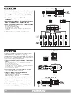
Front Panel Start Sequence Button Control
The ASD-120 2.0 front panel Start Sequence button can be used as the primary
control to initiate a sequence. If the unit is programmed for Momentary Mode
(DIP 7 = ON), each time Start Sequence is depressed, the ASD-120 2.0 will tog-
gle between ON and OFF sequences. If the button is pressed and held for more
than six seconds, the ASD-120 2.0 will sequence to the OFF state.
The front Start Sequence button should only be used when the Key Switch is in
the REMOTE position with DIP 7 the MOM/MNT dip switch set to MOM (DIP 7 in
the UP position).
Push buttons in multiple locations can be used to initiate ON/OFF sequences.
Remote control options are discussed in the Momentary Mode Section.
Note:
The Start Sequence Button is disabled when DIP 6 is in GND ON mode
(Position UP).
Note:
Loss of AC Power in Momentary Mode will result in all Banks returning to
an OFF state when the utility service is restored.
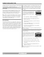
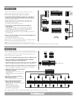
Remote Operating Modes
When the Key Switch is in the REMOTE position, the ASD-120 2.0 will respond as
configured by the switches behind the front panel cover plate. The ASD-120 2.0
can be programmed to respond to remote Momentary and sustained (Maintained)
trigger conditions. The unit can be triggered by the presence or absence of
contact closures or a DC voltage. The ASD-120 2.0 can also be used to trigger
remote equipment using the same type of trigger conditions.
The ASD-120 2.0 and similar equipment (available from FURMAN and other
sources) can be controlled in parallel with a control signal wired from a single
switch. Also, control connections can be made in series with various units trig-
gered from an event occurring at another piece of equipment. An infinite variety
of connection schemes using any combination of these two methods is possible.
The momentary mode is only used with trigger signals that are of a short duration
such as a push button. Equipment compatible with this type of trigger can be
connected in a way that permits the initialization of a sequence from push buttons
in multiple locations.
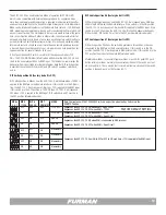
Signal level relay contacts A thru F are provided at the rear panel of the ASD-120
2.0 which can be used for the purpose of triggering external equipment. The
contacts can be configured as a group as normally open (NO) or normally
closed (NC).
When the key switch is in either the ON or OFF position, the ASD-120’s sequenc-
ing circuits will not respond to the rear panel remote control inputs. If the key
switch is returned to the REMOTE position, the signals supplied to the rear panel
remote inputs will again control the unit.


