

18
PRODUCT INSTALLATION EXAMPLES
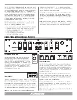
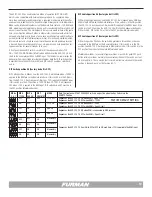
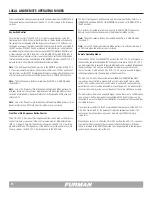
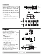
ASD-120 2.0 ACTIVATED BY MULTIPLE RS-2 REMOTE SWITCH LOCATIONS
WITH ONE PRIMARY SWITCH AND FIRE ALARM
ON
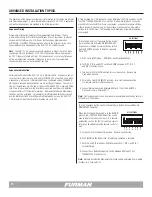
ASD-120 2.0 DIP SETTINGS
FIRE ALARM
DLY
ADJ
1 2 3 4 5 6 7
ALWAYS ON
ALWAYS OFF
S
E
Q
SET TO
MIDDLE
POSITION
12V STAT REM GND
12V STAT REM GND
ASD-120 2.0
PRIMARY SWITCH RS-2
LOCATION #1
JUMPER J-2 ON
RS-2
LOCATION #2
FORCE
NO
C
NC
RS-2
LOCATION #3
12V
STAT
REM
GND
12V
STAT
REM
GND
ASD-120 2.0
Diagram #2 illustrates multiple Furman RS-2 Remote System Control Panels controlling the
ASD-120 2.0 sequencer while one RS-2 Remote System Control Panel acts as the Primary
Security Key Switch:
1. All RS-2 terminal locations are connected to the ASD-120 2.0 REMOTE terminals,
pole to pole:
• 12V to 12V, REM to REM, STAT to STAT, and GND to GND.
2. Dedicate a single RS-2 as a Primary Switch.
• Set J-2 jumper location, place suitcase jumper across both pins.
• When this Primary RS-2 Key Switch is set in “DISABLED” location all other parallel
connected RS-2 Remote System Control Panels “buttons” will be disabled.
3. Configure ASD-120 2.0 Multi-Function DIP for Normally Closed &
Momentary Mode.
• DIP 4 UP – (NO), verify factory default.
• DIP 7 UP – MOM, verify Momentary Mode.
• Configure 2.0 Multi-Function DIP switches 1, 2 & 3 to desired delay time interval.
• Ensure All Bypass Set DIP switches are selected as desired.
• Set ASD-120 2.0 Key Switch to Remote.
All RS-2 Remote System Control Panel or Momentary locations will activate the ASD-120 2.0 program sequence. The Primary RS-2 Remote System Control Panel has priority over the other control panels.
When the key switch of the Primary RS-2 is set to the “DISABLED” position the operation of the other RS-2 Control Panel locations will be defeated.
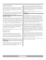
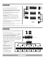
M-8S WITH ASD-120 2.0
ON
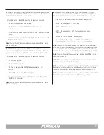
ASD-120 2.0 DIP SETTINGS
DLY
ADJ
1 2 3 4 5 6 7
ALWAYS ON
ALWAYS OFF
S
E
Q
SET TO
MIDDLE
POSITION
FORCE
RS-1 REMOTE SWITCH
12V STAT REM GND
12V STAT REM GND
ASD-120 2.0 REMOTE PORT
12V ON
12V OFF
GND
ON
MOM
MNT
DLY
ADJ
1 2 3
1
2
3
REMOTE PORT
12V STAT REM GND
SECONDARY ASD-120 2.0
1.
Configure ASD-120 2.0 Multi-Function DIP Switch Set for Normally Closed &
Maintained Mode ON
.
• DIP 4 UP – (NO), verify factory default.
• DIP 7 DOWN – MNT, verify factory default.
• Configure ASD-120 2.0 Multi-Function DIP switches 1, 2 & 3 set for desired delay time.
• Ensure All Bypass Set DIP switches are selected as desired.
• Set ASD-120 2.0 Key Switch to Remote.
When the RS-1 remote switch is turned to ON it will trigger the ASD-120 2.0 to begin its
sequence.
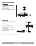
DIAGRAM EXAMPLE 1
DIAGRAM EXAMPLE 2


