Furman ASD-120 2.0 Скачать руководство пользователя страница 18

17

STATUS Output

The STATUS terminal is an output that may be used to illuminate an LED at 
remote locations to indicate the ASD-120 2.0 has active Delay Banks.  If it is high 
(+12V), the unit is on (or at least in the process of sequencing on); if low, the unit 
is off (or sequencing off). Simply connect the indicator LED between STATUS and 
GND (a series resistor is not required). If the LED does not light when the switch 
is in the ON position, check the polarity and reverse the LED leads. The STATUS 
output is a 12V source, current limited to 10 mA.  If you wish to generate a STA-
TUS output voltage to a confidence monitor or an indicator, please use a 1k Ohm 
1/4-watt resistor in series with the LED. 

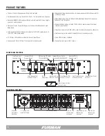
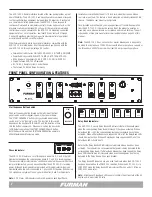
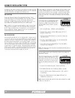
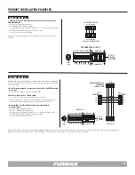
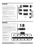
REMOTE Interface – Rear Panel 4 pin Connector

The four pin Remote Interface terminal strip on the back of the ASD-120 2.0 
allows a switch (or parallel switches) to be connected to turn the unit on and off 
from a distance. In the most basic configuration, only two Class 2 wires and an 
SPST switch or relay contacts are needed to initiate an on or off sequence. The 
switch may be either a momentary or maintained-contact type. An LED may also 
be installed at the remote end to indicate when power is on, but this will require 
a third wire.

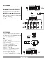
DELAY OUTPUTS – Rear Panel 8 pin Connector

The DELAY OUTPUTS are a series of six isolated dry switch contacts that are 
intended to interface with the end user’s low voltage power switching devices.  
DELAY outputs A through F correspond to sequence stages A through F.  The 
N.C. (normally closed) and NO (normally open) relay contacts of all DELAY relays 
are combined into two separate NO and NC switch buses which are brought out 
to the rear panel DELAY Output interface.  This allows the end user to select the 
switching preference, either N.C. or NO, to be used for connected equipment.  
The user may also connect either 12V or GND to the N.O. or N.C. switch contacts.    
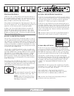
Note: 

 A front panel Delay Bank LED indicator confirms the state of the DC relay 

as well as its associated AC duplex. 

FORCE OFF Interface – Rear Panel 2 pin Connector

The FORCE OFF input provides a method of immediately turning off all Bank 
relays and output circuits.  This input can be connected to a fire alarm panel to 
disconnect power to all loads in the event of an emergency.  DIP 4 behind the 
front panel cover plate controls the trigger condition that forces the unit OFF.  
All the Delay Bank LEDS will blink in unison if a FORCE OFF state is activated.  
To reset the ASD-120 2.0, turn the Key Switch to the OFF position to clear 
or if necessary, cede the service power to the ASD-120 2.0 to reset and clear.

Note: 

 The ASD-120 2.0 is disabled when DIP 4 is set for (N.C.) mode.  Factory 

DIP 4 (N.O.) mode is recommended. Only a short across the Forced Off terminals 
will activate the ASD-120 2.0 if DIP 4 is in the (N.C.) mode. This DIP setting is 
reserved for alarm systems.   Factory default for DIP 4 is (N.O) mode position UP.  

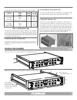
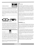
SIGNAL WIRE CONSIDERATIONS

Furman recommends that control signal wires be 24 to 28 awg. this type of 
wire is commonly available and works well. Generally, the choice is dependent 
on the amount connected equipment to be utilized through any one of the three 
interfaces REMOTE, DELAY OUTPUTS or FORCE OFF.  Wire nuts may be required 
in  situations where many pieces of controlled equipment share the same pin.  
Please note the low-voltage control signal must establish electrical continuity in 
order to be reliable and craftsmanship is a must.   

POWER DISTRIBUTION DESIGN CONSIDERATIONS

Furman is known for power distribution and surge protection, however it should 
be noted the design of the new ASD-120 2.0 only provides surge protection on 
its own internal components.  There is neither surge protection on the Delay Bank 
Duplex Outlets nor transient protection for the low-level DC contacts.  Any con-
ductor can provide a pathway for an electrical transient event, so all conductors 
should be addressed when formulating strategies for surge protection.  Please 
call Furman for information and details on how system installs can be designed 
for maximum protection from electrical transient events.  

Содержание ASD-120 2.0

Страница 1: ...PUT 120 3 208 240 VAC 14400 WATTS 120 AMPS MAX 20A MAX DELAY A 20A MAX DELAY B 20A MAX DELAY C 20A MAX DELAY D 20A MAX DELAY E 20A MAX DELAY F FORCE OFF DELAY OUTPUTS REMOTE NC A B C D E F NO 12V STAT...

Страница 2: ...ET CONFIER LA MAINTENANCE A UN T ECHNICIEN QUALIFIE DRY RELAY CONTACTS RATING 48V 1 AMP This box should include the following items 1 Model ASD 120 2 0 2 Two adjustable rear rack mounting ears 3 Secu...

Страница 3: ...ASD 120 2 0 please use the Direct Current 12V and REM terminals of the ASD 120 2 0 to provide the DC control signal to the REM input of the older ASD 120 product Ground loops at the control terminals...

Страница 4: ...ND If the loads are balanced the neutral cur rent will be zero but if the load is predominately on one phase the neutral must support the entire load current Since phases are distributed to different...

Страница 5: ...ENCE REMOTE DLY ADJ DELAY A DELAY B DELAY C PHASE X Y Z DELAY D DELAY E DELAY F OFF ON 1 2 3 4 5 6 7 ALWAYS ON ALWAYS OFF ASD 120 2 0 120 AMP POWER SEQUENCER SEE COVER PLATE START SEQUENCE REMOTE DLY...

Страница 6: ...AY F OFF ON ASD 120 2 0 120 AMP POWER SEQUENCER Security Cover to Protect Program Settings 1 5 Cable Clamp Input 120V Phase Six 20A duplex outlets Force Off 2 Pin Phoenix type Connector Remote 4 pin P...

Страница 7: ...ower of 14 4kW Higher levels of power can be achieved by connecting additional Furman sequencers or other power conditioning products including additional ASD 120 2 0 units Furman products provide a p...

Страница 8: ...l of the Delay Bank LEDs should be off Note that the Delay Bank LED indicators only indicate when a bank has been activated The indicators do not guarantee that power is being delivered to the corresp...

Страница 9: ...ector and the front panel START SEQUENCE push button switch Security Cover Shield and DIP Switch Program Interface The ASD 120 2 0 had two configuration DIP switches that are located underneath a secu...

Страница 10: ...1 minute maximum time delay DIP 2 adds 2 minutes and DIP 3 adds 4 minutes Please note these time delays are cumulative If all three DIP switches are in the UP position the maximum allowable time delay...

Страница 11: ...at once once any Momentary switch button is pushed including Remote Momentary switches As mentioned multiple momen tary remote contacts should be used if more than one remote power up location is des...

Страница 12: ...tary Maintained Sets local mode and remote contact closure preference for either Momentary or Maintained switches Note Momentary mode overrides DIP 5 and 6 Sequence Bypass DIP Switch DIP position ON A...

Страница 13: ...0 Delay outlets are OFF To use the STAT terminal output simply connect an LED between the STAT and GND with the Cathode flat side of the LED oriented toward the GND pin Pin 4 Do not use a series curr...

Страница 14: ...e set to OFF A time delayed On or Off sequence can be initiated at the front panel Key Switch the START SEQUENCE button or using the 4 Pin Remote Interface The config uration Multi Function DIP switch...

Страница 15: ...using external 5 to 30VDC power supply In this mode an external power supply will prevent the ASD 120 2 0 from sequencing ON The ASD 120 2 0 will automatically sequence ON when the DC power is remove...

Страница 16: ...uences If the button is pressed and held for more than six seconds the ASD 120 2 0 will sequence to the OFF state The front Start Sequence button should only be used when the Key Switch is in the REMO...

Страница 17: ...state until a connection is present between the REM and GND terminals or between the 12V and REM terminals DIP 7 switch is set in the down position MNT for operation in Maintained Mode And when utiliz...

Страница 18: ...ate of the DC relay as well as its associated AC duplex FORCE OFF Interface Rear Panel 2 pin Connector The FORCE OFF input provides a method of immediately turning off all Bank relays and output circu...

Страница 19: ...ry Mode DIP 4 UP NO verify factory default DIP 7 UP MOM verify Momentary Mode Configure 2 0 Multi Function DIP switches 1 2 3 to desired delay time interval Ensure All Bypass Set DIP switches are sele...

Страница 20: ...Delay Banks A through F Diagram Example 4 A Furman M 8S Sequencer triggered by an optional RS 1 Remote System Control Panel activates a Furman ASD 120 2 0 Sequencers at another in house location Diagr...

Страница 21: ...SD 120 2 0 ADVANCED INSTALLATION WITH FURMAN CN SERIES AND REMOTE RS 1 SWITCH ON ON CN 2400S DIP SETTINGS ASD 120 2 0 DIP SETTINGS FIRE ALARM NO C NC FORCE REMOTE 12V STAT REM GND 12V STAT REM GND DLY...

Страница 22: ...rs one per output Configuration Switches Front panel hidden by security cover 3 maximum delay switches 1 2 and 4 minute Force Off NO NC 12V mode On Off GND mode On Off Momentary Maintained mode select...

Страница 23: ...orce and effect SERVICE NOTE All equipment being returned for repair must have an RMA Return Mate rials Authorization number To receive an RMA number please contact Furman Technical Services at techsu...

Страница 24: ...y the GND ON Maintained Mode should be used Note GND to REM pins should be used for remote triggers with applied DC voltages 5V to 30VDC at REM ASD 120 2 0 PROGRAMMING SUMMARY DIP 7 MOM MNT Maintained...

Отзывы: