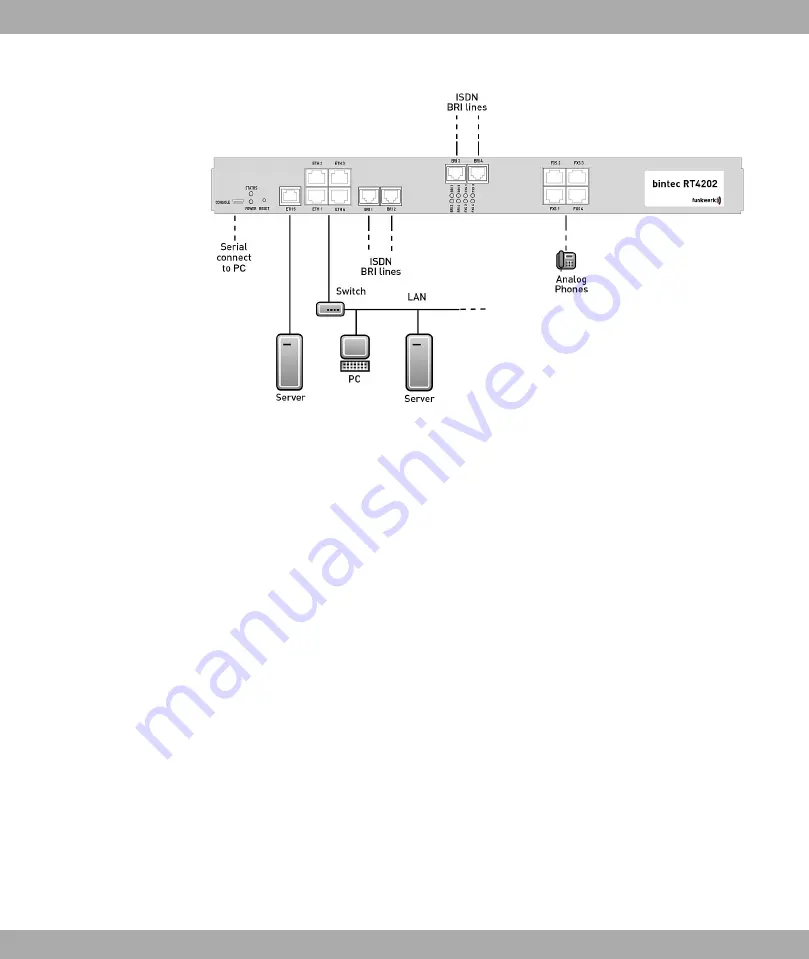
Fig. 2: Connection options using the example of
bintec RT4202
When setting up and connecting, carry out the steps in the following sequence (refer to the
connection diagrams for the individual devices in chapter
on page 19):
(1)
Affix the rubber feet supplied to the marked areas on the underside of the device.
(2)
Place your device on a fixed, even surface or install your device in a 19 inch cabinet
using the supplied bracket.
(3)
LAN
For the standard configuration of your device via Ethernet, connect the first switch
port (ETH1) of your device to your LAN using the Ethernet cable supplied. The
device automatically detects whether it is connected to a switch or directly to a PC.
(4)
ADSL (only bintec R3002 and bintec RT3002)
Connect the DSL interface (DSL) of your device to the DSL output of the splitter us-
ing the DSL cable supplied.
(5)
SHDSL (only bintec R3802)
Connect the SHDSL interface (SHDSL) of your device to the SHDSL connection us-
ing the DSL cable supplied.
(6)
VDSL (only bintec R3502 and bintec RT3502)
Connect the VDSL2 interface (VDSL) of your device to the VDSL connection using
the VDSL cable supplied.
(7)
Mains connection
Connect the device to a plug socket. The power connection is located on the back of
the device.
You can set up further connections as required:
Funkwerk Enterprise Communications GmbH
3 Installation
bintec Rxxx2/RTxxx2
7


