


11-10
SPARC Enterprise M4000/M5000 Servers Service Manual • December 2010
11.2.3
Installing Memory:
■
Only half or fully populated memory boards may be installed.
■
In Uni-XSB mode, 1, 2 or 4 memory boards can be installed per PSB, all must have
the same capacity. (3 memory boards is not allowed).
■
In Quad-XSB mode, each CPU module must have 1 half populated memory board
or 1 fully populated memory board; capacity can be different.
11.2.4
Accessing the DIMMs
Caution –
There is an electrical hazard if the power cords are not disconnected. All
power cords must be disconnected to completely remove power from the server.
1. Power off the server.
This step includes turning the key switch to the Service position, confirming that
the POWER LED is off, and disconnecting power cables. See
“Powering the Server Off Using Software” on page 4-12
Caution –
To prevent the equipment rack from tipping over, you must deploy the
antitilt feature, if applicable, before you slide the server out of the equipment rack.
Note –
When drawing out the SPARC Enterprise M4000/M5000 Server to the front,
release the cable tie holding the PCI cables on the rear of the server.
2. Remove the top cover.
This step includes deploying the rack’s antitilt features (if applicable), sliding the
server out of the equipment rack, and removing the top cover. See
“Removing the Top Cover” on page 5-5
Caution –
Use proper ESD grounding techniques when handling components. See
Section 1.1, “Safety Precautions” on page 1-1
.
3. Remove the memory board from the server.
See
Section 11.1.2, “Removing the Memory Board” on page 11-5
.
Содержание SPARC Enterprise M4000
Страница 4: ......
Страница 27: ...Chapter 2 Fault Isolation 2 3 FIGURE 2 2 Diagnostic Method Flow Chart Traditional Data Collection ...
Страница 62: ...2 38 SPARC Enterprise M4000 M5000 Servers Service Manual December 2010 ...
Страница 85: ...Chapter 5 Internal Components Access 5 3 FIGURE 5 1 Loosening the Captive Screws on the Shipping Brackets ...
Страница 89: ...Chapter 5 Internal Components Access 5 7 FIGURE 5 4 Removing the M5000 Server Top Cover ...
Страница 126: ...6 34 SPARC Enterprise M4000 M5000 Servers Service Manual December 2010 ...
Страница 132: ...7 6 SPARC Enterprise M4000 M5000 Servers Service Manual December 2010 ...
Страница 151: ...Chapter 8 I O Unit Replacement 8 19 FIGURE 8 12 Installing the DC DC Converter Without a DC DC Converter Retainer ...
Страница 155: ...Chapter 8 I O Unit Replacement 8 23 FIGURE 8 14 Removing the I O Unit DC DC Converter Riser and DC DC Converter DDC_B 0 ...
Страница 158: ...8 26 SPARC Enterprise M4000 M5000 Servers Service Manual December 2010 ...
Страница 179: ...Chapter 10 Fan Modules Replacement 10 15 FIGURE 10 6 Removing the M4000 Server 172 mm Fan Backplane ...
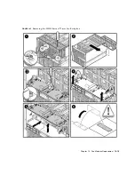
Страница 183: ...Chapter 10 Fan Modules Replacement 10 19 FIGURE 10 7 Removing the M5000 Server 172 mm Fan Backplane ...
Страница 221: ...Chapter 13 Motherboard Unit Replacement 13 9 FIGURE 13 4 Removing the M5000 Server Motherboard Unit ...
Страница 245: ...Chapter 14 Backplane Unit Replacement 14 11 FIGURE 14 4 Removing the M5000 Server Backplane ...
Страница 248: ...14 14 SPARC Enterprise M4000 M5000 Servers Service Manual December 2010 ...
Страница 254: ...15 6 SPARC Enterprise M4000 M5000 Servers Service Manual December 2010 FIGURE 15 3 Removing the Operator Panel ...
Страница 256: ...15 8 SPARC Enterprise M4000 M5000 Servers Service Manual December 2010 ...
Страница 288: ...E 6 SPARC Enterprise M4000 M5000 Servers Service Manual December 2010 ...
Страница 292: ...F 4 SPARC Enterprise M4000 M5000 Servers Service Manual December 2010 FIGURE F 2 Hook and Loop Tape Locations ...
Страница 303: ...Appendix F Air Filters F 15 11 Perform Steps 1 through 8 of Section F 1 1 Command Operations Procedures on page F 2 ...
Страница 304: ...F 16 SPARC Enterprise M4000 M5000 Servers Service Manual December 2010 ...
Страница 308: ...G 4 SPARC Enterprise M4000 M5000 Servers Service Manual December 2010 ...


