Chapter 13
Motherboard Unit Replacement
13-21
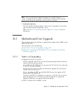
9. Update the XCP version.
For the firmware updating procedures, see the
SPARC Enterprise
M3000/M4000/M5000/M8000/M9000 Servers XSCF User’s Guide
.
10. Replace the existing MBU with the new MBU.
For details on how to replace the MBU, see
Section 13.1, “Motherboard Unit
. To replace the CPUM at the same time, see
Section 12.1, “CPU Module Replacement” on page 12-1
.
Caution –
Before replacing the MBU, remove the power cable from the power
supply unit. After the replacement, reconnect the power cable to the power supply
unit.
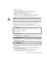
11. Log in to the XSCF again, using an account with the
platadm
privilege.
12. Perform and initial diagnosis of the newly installed MBU.
The following example shows a test after adding PSB#01 to a SPARC Enterprise
M5000 server:
13. Confirm that the replaced component has been recognized by the server, and the
error indicator asterisk (*) is not displayed.
14. Use the
showlogs error -v
command and the
showstatus
(8) command, to
confirm that no errors occurred.
15. Change the mode switch setting on the operator panel from Service to Locked,
to put it back.
16. If you replace the CPUM at the same time, set up and confirm the CPU
operational mode of the domain.
For details, see the chapter, "Setting Up XSCF." in the
SPARC Enterprise
M3000/M4000/M5000/M8000/M9000 Servers XSCF User’s Guide
.
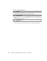
XSCF>
testsb 01
Initial diagnosis is about to start. Continue? [y|n] :
y
Initial diagnosis is executing.
Initial diagnosis has completed.
XSB Test Fault
---- ------- --------
01 Passed Normal
XSCF>
showhardconf -M
XSCF>
showlogs error -v
XSCF>
showstatus
Содержание SPARC Enterprise M4000
Страница 4: ......
Страница 27: ...Chapter 2 Fault Isolation 2 3 FIGURE 2 2 Diagnostic Method Flow Chart Traditional Data Collection ...
Страница 62: ...2 38 SPARC Enterprise M4000 M5000 Servers Service Manual December 2010 ...
Страница 85: ...Chapter 5 Internal Components Access 5 3 FIGURE 5 1 Loosening the Captive Screws on the Shipping Brackets ...
Страница 89: ...Chapter 5 Internal Components Access 5 7 FIGURE 5 4 Removing the M5000 Server Top Cover ...
Страница 126: ...6 34 SPARC Enterprise M4000 M5000 Servers Service Manual December 2010 ...
Страница 132: ...7 6 SPARC Enterprise M4000 M5000 Servers Service Manual December 2010 ...
Страница 151: ...Chapter 8 I O Unit Replacement 8 19 FIGURE 8 12 Installing the DC DC Converter Without a DC DC Converter Retainer ...
Страница 155: ...Chapter 8 I O Unit Replacement 8 23 FIGURE 8 14 Removing the I O Unit DC DC Converter Riser and DC DC Converter DDC_B 0 ...
Страница 158: ...8 26 SPARC Enterprise M4000 M5000 Servers Service Manual December 2010 ...
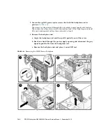
Страница 179: ...Chapter 10 Fan Modules Replacement 10 15 FIGURE 10 6 Removing the M4000 Server 172 mm Fan Backplane ...
Страница 183: ...Chapter 10 Fan Modules Replacement 10 19 FIGURE 10 7 Removing the M5000 Server 172 mm Fan Backplane ...
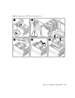
Страница 221: ...Chapter 13 Motherboard Unit Replacement 13 9 FIGURE 13 4 Removing the M5000 Server Motherboard Unit ...
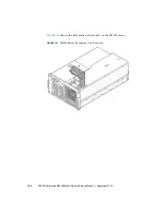
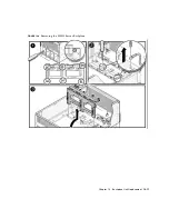
Страница 245: ...Chapter 14 Backplane Unit Replacement 14 11 FIGURE 14 4 Removing the M5000 Server Backplane ...
Страница 248: ...14 14 SPARC Enterprise M4000 M5000 Servers Service Manual December 2010 ...
Страница 254: ...15 6 SPARC Enterprise M4000 M5000 Servers Service Manual December 2010 FIGURE 15 3 Removing the Operator Panel ...
Страница 256: ...15 8 SPARC Enterprise M4000 M5000 Servers Service Manual December 2010 ...
Страница 288: ...E 6 SPARC Enterprise M4000 M5000 Servers Service Manual December 2010 ...
Страница 292: ...F 4 SPARC Enterprise M4000 M5000 Servers Service Manual December 2010 FIGURE F 2 Hook and Loop Tape Locations ...
Страница 303: ...Appendix F Air Filters F 15 11 Perform Steps 1 through 8 of Section F 1 1 Command Operations Procedures on page F 2 ...
Страница 304: ...F 16 SPARC Enterprise M4000 M5000 Servers Service Manual December 2010 ...
Страница 308: ...G 4 SPARC Enterprise M4000 M5000 Servers Service Manual December 2010 ...

