


13-20
SPARC Enterprise M4000/M5000 Servers Service Manual • December 2010
For details on the configuration in each domain which consists of processors of
different types, see the
SPARC Enterprise M3000/M4000/M5000/M8000/M9000
Servers XSCF User’s Guide
. In the document, see the section of "Domain Mode
Configuration" which describes "Mounted Processors and CPU Operational
Modes."
13.3.2
Replacing a Motherboard Unit as an Upgrade in
an Existing Domain
1. Update the Oracle Solaris OS to the minimum required version which is
described in the Product Notes of the appropriate XCP version, or apply the
mandatory patches.
2. Prior to replacing with new MBU, apply the appropriate patches to the software
in use, if necessary.
3. Log in to XSCF using an account with the
platadm
privilege.
4. Use the
showstatus
(8) command to confirm that a component in Faulted or
Deconfigured status does not exist.
If there is no problem, the message of "
No failures found in System
Initialization
" appears. If case of other messages, contact a certified service
engineer before proceeding to the next step.
5. Turn off the power to all domains.
6. Confirm that the target domain is shut down.
7. Change the mode switch setting on the operator panel from Locked to Service.
8. Collect an XSCF snapshot to archive the system status prior to upgrade.
This data will be helpful, in case any problem occurred during the upgrade.
XSCF>
showstatus
XSCF>
poweroff -a
XSCF>
showlogs power
XSCF>
snapshot -t
user
@
host
:
directory
Содержание SPARC Enterprise M4000
Страница 4: ......
Страница 27: ...Chapter 2 Fault Isolation 2 3 FIGURE 2 2 Diagnostic Method Flow Chart Traditional Data Collection ...
Страница 62: ...2 38 SPARC Enterprise M4000 M5000 Servers Service Manual December 2010 ...
Страница 85: ...Chapter 5 Internal Components Access 5 3 FIGURE 5 1 Loosening the Captive Screws on the Shipping Brackets ...
Страница 89: ...Chapter 5 Internal Components Access 5 7 FIGURE 5 4 Removing the M5000 Server Top Cover ...
Страница 126: ...6 34 SPARC Enterprise M4000 M5000 Servers Service Manual December 2010 ...
Страница 132: ...7 6 SPARC Enterprise M4000 M5000 Servers Service Manual December 2010 ...
Страница 151: ...Chapter 8 I O Unit Replacement 8 19 FIGURE 8 12 Installing the DC DC Converter Without a DC DC Converter Retainer ...
Страница 155: ...Chapter 8 I O Unit Replacement 8 23 FIGURE 8 14 Removing the I O Unit DC DC Converter Riser and DC DC Converter DDC_B 0 ...
Страница 158: ...8 26 SPARC Enterprise M4000 M5000 Servers Service Manual December 2010 ...
Страница 179: ...Chapter 10 Fan Modules Replacement 10 15 FIGURE 10 6 Removing the M4000 Server 172 mm Fan Backplane ...
Страница 183: ...Chapter 10 Fan Modules Replacement 10 19 FIGURE 10 7 Removing the M5000 Server 172 mm Fan Backplane ...
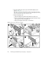
Страница 221: ...Chapter 13 Motherboard Unit Replacement 13 9 FIGURE 13 4 Removing the M5000 Server Motherboard Unit ...
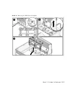
Страница 245: ...Chapter 14 Backplane Unit Replacement 14 11 FIGURE 14 4 Removing the M5000 Server Backplane ...
Страница 248: ...14 14 SPARC Enterprise M4000 M5000 Servers Service Manual December 2010 ...
Страница 254: ...15 6 SPARC Enterprise M4000 M5000 Servers Service Manual December 2010 FIGURE 15 3 Removing the Operator Panel ...
Страница 256: ...15 8 SPARC Enterprise M4000 M5000 Servers Service Manual December 2010 ...
Страница 288: ...E 6 SPARC Enterprise M4000 M5000 Servers Service Manual December 2010 ...
Страница 292: ...F 4 SPARC Enterprise M4000 M5000 Servers Service Manual December 2010 FIGURE F 2 Hook and Loop Tape Locations ...
Страница 303: ...Appendix F Air Filters F 15 11 Perform Steps 1 through 8 of Section F 1 1 Command Operations Procedures on page F 2 ...
Страница 304: ...F 16 SPARC Enterprise M4000 M5000 Servers Service Manual December 2010 ...
Страница 308: ...G 4 SPARC Enterprise M4000 M5000 Servers Service Manual December 2010 ...


