


11-6
SPARC Enterprise M4000/M5000 Servers Service Manual • December 2010
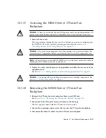
11.1.3
Installing the Memory Board
Caution –
Do not force
the memory board into a slot. Doing so can cause damage to
the board and server.
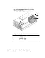
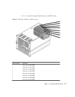
1. Place the memory board in the server.
The levers should be extended as far as possible.
Note –
Place the Memory Boards into the original locations.
2. Gently push the memory board into the server until it stops.
3. Push the levers inward simultaneously to seat the memory board.
11.1.4
Securing the Server
1. Install the top cover.
This step includes sliding the server in to the equipment rack and restoring the
rack antitilt features to their original position. See
Section 5.2.2, “Replacing the Top
.
2. Power on the server.
This step includes reconnecting power cables, verifying the state of the LEDs, and
turning the keyswitch to the Locked position. See
Server On Using Software” on page 4-13
Note –
If the Oracle Solaris automatic booting is set, use the
sendbreak -d
domain_id
command after the display console banner is displayed but before the
system starts booting the operating system to get the
ok
prompt.
3. Confirm the hardware.
This step includes running programs to be certain all components are mounted
again and then booting the operating system.
Refer to
Section 4.3.2, “Verifying Hardware Operation” on page 4-9
for more
information.
Содержание SPARC Enterprise M4000
Страница 4: ......
Страница 27: ...Chapter 2 Fault Isolation 2 3 FIGURE 2 2 Diagnostic Method Flow Chart Traditional Data Collection ...
Страница 62: ...2 38 SPARC Enterprise M4000 M5000 Servers Service Manual December 2010 ...
Страница 85: ...Chapter 5 Internal Components Access 5 3 FIGURE 5 1 Loosening the Captive Screws on the Shipping Brackets ...
Страница 89: ...Chapter 5 Internal Components Access 5 7 FIGURE 5 4 Removing the M5000 Server Top Cover ...
Страница 126: ...6 34 SPARC Enterprise M4000 M5000 Servers Service Manual December 2010 ...
Страница 132: ...7 6 SPARC Enterprise M4000 M5000 Servers Service Manual December 2010 ...
Страница 151: ...Chapter 8 I O Unit Replacement 8 19 FIGURE 8 12 Installing the DC DC Converter Without a DC DC Converter Retainer ...
Страница 155: ...Chapter 8 I O Unit Replacement 8 23 FIGURE 8 14 Removing the I O Unit DC DC Converter Riser and DC DC Converter DDC_B 0 ...
Страница 158: ...8 26 SPARC Enterprise M4000 M5000 Servers Service Manual December 2010 ...
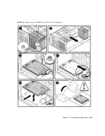
Страница 179: ...Chapter 10 Fan Modules Replacement 10 15 FIGURE 10 6 Removing the M4000 Server 172 mm Fan Backplane ...
Страница 183: ...Chapter 10 Fan Modules Replacement 10 19 FIGURE 10 7 Removing the M5000 Server 172 mm Fan Backplane ...
Страница 221: ...Chapter 13 Motherboard Unit Replacement 13 9 FIGURE 13 4 Removing the M5000 Server Motherboard Unit ...
Страница 245: ...Chapter 14 Backplane Unit Replacement 14 11 FIGURE 14 4 Removing the M5000 Server Backplane ...
Страница 248: ...14 14 SPARC Enterprise M4000 M5000 Servers Service Manual December 2010 ...
Страница 254: ...15 6 SPARC Enterprise M4000 M5000 Servers Service Manual December 2010 FIGURE 15 3 Removing the Operator Panel ...
Страница 256: ...15 8 SPARC Enterprise M4000 M5000 Servers Service Manual December 2010 ...
Страница 288: ...E 6 SPARC Enterprise M4000 M5000 Servers Service Manual December 2010 ...
Страница 292: ...F 4 SPARC Enterprise M4000 M5000 Servers Service Manual December 2010 FIGURE F 2 Hook and Loop Tape Locations ...
Страница 303: ...Appendix F Air Filters F 15 11 Perform Steps 1 through 8 of Section F 1 1 Command Operations Procedures on page F 2 ...
Страница 304: ...F 16 SPARC Enterprise M4000 M5000 Servers Service Manual December 2010 ...
Страница 308: ...G 4 SPARC Enterprise M4000 M5000 Servers Service Manual December 2010 ...


