Chapter 4
FRU Replacement Preparation
4-9
4.3.2
Verifying Hardware Operation
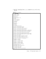
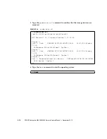
1. Type the
showhardconf
command to confirm the new component is installed.
EXAMPLE 4-3
showhardconf
XSCF> showhardconf
SPARC Enterprise M5000;
+ Serial:BCF07500B6; Operator_Panel_Switch:Locked;
+ Power_Supply_System:Dual; SCF-ID:XSCF#0;
+ System_Power:On; System_Phase:Cabinet Power On;
Domain#0 Domain_Status:Initialization Phase;
Domain#1 Domain_Status:Initialization Phase;
MBU_B Status:Normal; Ver:0201h; Serial:BC07490823 ;
+ FRU-Part-Number:CF00541-0478 05
/541-0478-05
;
+ Memory_Size:64 GB;
CPUM#0-CHIP#0 Status:Normal; Ver:0501h; Serial:PP0723016Q
;
+ FRU-Part-Number:CA06761-D204 A0
/LGA-JUPP-01
;
+ Freq:2.530 GHz; Type:32;
+ Core:4; Strand:2;
:
CPUM#3-CHIP#1 Status:Normal; Ver:0501h; Serial:PP074804E9
;
+ FRU-Part-Number:CA06761-D204 A0
/LGA-JUPP-01
;
+ Freq:2.530 GHz; Type:32;
+ Core:4; Strand:2;
MEMB#0 Status:Normal; Ver:0101h; Serial:BF09061G0E ;
+ FRU-Part-Number:CF00541-0545 06
/541-0545-06
;
MEM#0A Status:Normal;
+ Code:c1000000000000005372T128000HR3.7A
356d-0d016912;
+ Type:1A; Size:1 GB;
:
MEM#3B Status:Normal;
+ Code:c1000000000000004572T128000HR3.7A
252b-04123424;
+ Type:1A; Size:1 GB;
:
MEMB#7 Status:Normal; Ver:0101h; Serial:BF09061GBA ;
+ FRU-Part-Number:CF00541-0545 06
/541-0545-06
;
MEM#0A Status:Normal;
+ Code:2cffffffffffffff0818HTF12872Y-53EB3 0300-d504600c;
+ Type:1A; Size:1 GB;
:
MEM#3B Status:Normal;
+ Code:7f7ffe00000000004aEBE10RD4AGFA-5C-E 3020-2229c19c;
+ Type:1A; Size:1 GB;
Содержание SPARC Enterprise M4000
Страница 4: ......
Страница 27: ...Chapter 2 Fault Isolation 2 3 FIGURE 2 2 Diagnostic Method Flow Chart Traditional Data Collection ...
Страница 62: ...2 38 SPARC Enterprise M4000 M5000 Servers Service Manual December 2010 ...
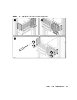
Страница 85: ...Chapter 5 Internal Components Access 5 3 FIGURE 5 1 Loosening the Captive Screws on the Shipping Brackets ...
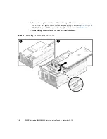
Страница 89: ...Chapter 5 Internal Components Access 5 7 FIGURE 5 4 Removing the M5000 Server Top Cover ...
Страница 126: ...6 34 SPARC Enterprise M4000 M5000 Servers Service Manual December 2010 ...
Страница 132: ...7 6 SPARC Enterprise M4000 M5000 Servers Service Manual December 2010 ...
Страница 151: ...Chapter 8 I O Unit Replacement 8 19 FIGURE 8 12 Installing the DC DC Converter Without a DC DC Converter Retainer ...
Страница 155: ...Chapter 8 I O Unit Replacement 8 23 FIGURE 8 14 Removing the I O Unit DC DC Converter Riser and DC DC Converter DDC_B 0 ...
Страница 158: ...8 26 SPARC Enterprise M4000 M5000 Servers Service Manual December 2010 ...
Страница 179: ...Chapter 10 Fan Modules Replacement 10 15 FIGURE 10 6 Removing the M4000 Server 172 mm Fan Backplane ...
Страница 183: ...Chapter 10 Fan Modules Replacement 10 19 FIGURE 10 7 Removing the M5000 Server 172 mm Fan Backplane ...
Страница 221: ...Chapter 13 Motherboard Unit Replacement 13 9 FIGURE 13 4 Removing the M5000 Server Motherboard Unit ...
Страница 245: ...Chapter 14 Backplane Unit Replacement 14 11 FIGURE 14 4 Removing the M5000 Server Backplane ...
Страница 248: ...14 14 SPARC Enterprise M4000 M5000 Servers Service Manual December 2010 ...
Страница 254: ...15 6 SPARC Enterprise M4000 M5000 Servers Service Manual December 2010 FIGURE 15 3 Removing the Operator Panel ...
Страница 256: ...15 8 SPARC Enterprise M4000 M5000 Servers Service Manual December 2010 ...
Страница 288: ...E 6 SPARC Enterprise M4000 M5000 Servers Service Manual December 2010 ...
Страница 292: ...F 4 SPARC Enterprise M4000 M5000 Servers Service Manual December 2010 FIGURE F 2 Hook and Loop Tape Locations ...
Страница 303: ...Appendix F Air Filters F 15 11 Perform Steps 1 through 8 of Section F 1 1 Command Operations Procedures on page F 2 ...
Страница 304: ...F 16 SPARC Enterprise M4000 M5000 Servers Service Manual December 2010 ...
Страница 308: ...G 4 SPARC Enterprise M4000 M5000 Servers Service Manual December 2010 ...


