


4-6
SPARC Enterprise M4000/M5000 Servers Service Manual • December 2010
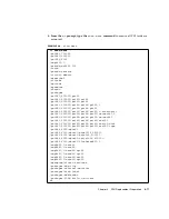
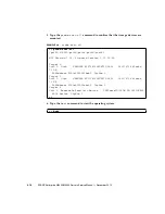
2. Type the
cfgadm
command to confirm the component is now connected.
4.2.4
Verifying Hardware Operation
●
Verify the state of the status LEDs.
The POWER LED should be On and the CHECK LED should not be On.
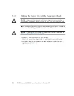
Note –
If the hard disk drive is the boot device, the hard disk will have to be
replaced using cold replacement procedures. However, active replacement can be
used if the boot disk can be isolated from the Oracle Solaris OS by disk mirroring
software and other software.
4.3
Hot Replacement
In hot replacement the Oracle Solaris OS does not need to be configured to allow the
component to be replaced. Depending on the FRU to be replaced, the FRU can either
be directly replaced or be inactivated or powered down using an XSCF command.
#
cfgadm -a
Ap_Id
Type
Receptacle
Occupant
Condition
iou#0-pci#0
etherne/hp
connected
configured
ok
iou#0-pci#1
fibre/hp
connected
configured
ok
iou#0-pci#2
pci-pci/hp
connected
configured
ok
Содержание SPARC Enterprise M4000
Страница 4: ......
Страница 27: ...Chapter 2 Fault Isolation 2 3 FIGURE 2 2 Diagnostic Method Flow Chart Traditional Data Collection ...
Страница 62: ...2 38 SPARC Enterprise M4000 M5000 Servers Service Manual December 2010 ...
Страница 85: ...Chapter 5 Internal Components Access 5 3 FIGURE 5 1 Loosening the Captive Screws on the Shipping Brackets ...
Страница 89: ...Chapter 5 Internal Components Access 5 7 FIGURE 5 4 Removing the M5000 Server Top Cover ...
Страница 126: ...6 34 SPARC Enterprise M4000 M5000 Servers Service Manual December 2010 ...
Страница 132: ...7 6 SPARC Enterprise M4000 M5000 Servers Service Manual December 2010 ...
Страница 151: ...Chapter 8 I O Unit Replacement 8 19 FIGURE 8 12 Installing the DC DC Converter Without a DC DC Converter Retainer ...
Страница 155: ...Chapter 8 I O Unit Replacement 8 23 FIGURE 8 14 Removing the I O Unit DC DC Converter Riser and DC DC Converter DDC_B 0 ...
Страница 158: ...8 26 SPARC Enterprise M4000 M5000 Servers Service Manual December 2010 ...
Страница 179: ...Chapter 10 Fan Modules Replacement 10 15 FIGURE 10 6 Removing the M4000 Server 172 mm Fan Backplane ...
Страница 183: ...Chapter 10 Fan Modules Replacement 10 19 FIGURE 10 7 Removing the M5000 Server 172 mm Fan Backplane ...
Страница 221: ...Chapter 13 Motherboard Unit Replacement 13 9 FIGURE 13 4 Removing the M5000 Server Motherboard Unit ...
Страница 245: ...Chapter 14 Backplane Unit Replacement 14 11 FIGURE 14 4 Removing the M5000 Server Backplane ...
Страница 248: ...14 14 SPARC Enterprise M4000 M5000 Servers Service Manual December 2010 ...
Страница 254: ...15 6 SPARC Enterprise M4000 M5000 Servers Service Manual December 2010 FIGURE 15 3 Removing the Operator Panel ...
Страница 256: ...15 8 SPARC Enterprise M4000 M5000 Servers Service Manual December 2010 ...
Страница 288: ...E 6 SPARC Enterprise M4000 M5000 Servers Service Manual December 2010 ...
Страница 292: ...F 4 SPARC Enterprise M4000 M5000 Servers Service Manual December 2010 FIGURE F 2 Hook and Loop Tape Locations ...
Страница 303: ...Appendix F Air Filters F 15 11 Perform Steps 1 through 8 of Section F 1 1 Command Operations Procedures on page F 2 ...
Страница 304: ...F 16 SPARC Enterprise M4000 M5000 Servers Service Manual December 2010 ...
Страница 308: ...G 4 SPARC Enterprise M4000 M5000 Servers Service Manual December 2010 ...


