


Chapter 5
Internal Components Access
5-5
5.2
Top Cover Remove and Replace
You must slide the server out of the equipment rack before removing the top cover.
5.2.1
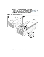
Removing the Top Cover
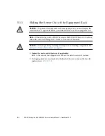
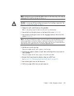
Caution –
To prevent the equipment rack from tipping over, you must deploy the
antitilt feature, if applicable, before you slide the server out of the equipment rack.
Note –
When drawing out the SPARC Enterprise M4000/M5000 Server to the front,
release the cable tie holding the PCI cables on the rear of the server.
Caution –
Use proper ESD grounding techniques when handling components. See
Section 1.1, “Safety Precautions” on page 1-1
.
1. Deploy the rack’s antitilt features (if applicable).
Refer to the rack manual for details on the rack’s antitilt features.
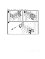
2. Loosen the four (4) captive screws at the front of the server (
3. Loosen the four (4) captive screws on the shipping brackets at the rear of the
system (
Note –
During installation the power cables should have been bundled into a loop
with enough slack to allow the system to slide out on the rails. This is called the
service loop. If this is not the case the power cables will have to be disconnected to
allow the server to pull all the way out of the equipment rack.
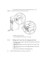
4. Pull the server to the fan stop.
The server automatically locks in place at the fan stop.
5. Push the green plastic releases on each slide rail and pull the server until it is
fully extended.
The server automatically locks in place when fully extended.
Содержание SPARC Enterprise M4000
Страница 4: ......
Страница 27: ...Chapter 2 Fault Isolation 2 3 FIGURE 2 2 Diagnostic Method Flow Chart Traditional Data Collection ...
Страница 62: ...2 38 SPARC Enterprise M4000 M5000 Servers Service Manual December 2010 ...
Страница 85: ...Chapter 5 Internal Components Access 5 3 FIGURE 5 1 Loosening the Captive Screws on the Shipping Brackets ...
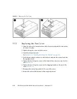
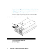
Страница 89: ...Chapter 5 Internal Components Access 5 7 FIGURE 5 4 Removing the M5000 Server Top Cover ...
Страница 126: ...6 34 SPARC Enterprise M4000 M5000 Servers Service Manual December 2010 ...
Страница 132: ...7 6 SPARC Enterprise M4000 M5000 Servers Service Manual December 2010 ...
Страница 151: ...Chapter 8 I O Unit Replacement 8 19 FIGURE 8 12 Installing the DC DC Converter Without a DC DC Converter Retainer ...
Страница 155: ...Chapter 8 I O Unit Replacement 8 23 FIGURE 8 14 Removing the I O Unit DC DC Converter Riser and DC DC Converter DDC_B 0 ...
Страница 158: ...8 26 SPARC Enterprise M4000 M5000 Servers Service Manual December 2010 ...
Страница 179: ...Chapter 10 Fan Modules Replacement 10 15 FIGURE 10 6 Removing the M4000 Server 172 mm Fan Backplane ...
Страница 183: ...Chapter 10 Fan Modules Replacement 10 19 FIGURE 10 7 Removing the M5000 Server 172 mm Fan Backplane ...
Страница 221: ...Chapter 13 Motherboard Unit Replacement 13 9 FIGURE 13 4 Removing the M5000 Server Motherboard Unit ...
Страница 245: ...Chapter 14 Backplane Unit Replacement 14 11 FIGURE 14 4 Removing the M5000 Server Backplane ...
Страница 248: ...14 14 SPARC Enterprise M4000 M5000 Servers Service Manual December 2010 ...
Страница 254: ...15 6 SPARC Enterprise M4000 M5000 Servers Service Manual December 2010 FIGURE 15 3 Removing the Operator Panel ...
Страница 256: ...15 8 SPARC Enterprise M4000 M5000 Servers Service Manual December 2010 ...
Страница 288: ...E 6 SPARC Enterprise M4000 M5000 Servers Service Manual December 2010 ...
Страница 292: ...F 4 SPARC Enterprise M4000 M5000 Servers Service Manual December 2010 FIGURE F 2 Hook and Loop Tape Locations ...
Страница 303: ...Appendix F Air Filters F 15 11 Perform Steps 1 through 8 of Section F 1 1 Command Operations Procedures on page F 2 ...
Страница 304: ...F 16 SPARC Enterprise M4000 M5000 Servers Service Manual December 2010 ...
Страница 308: ...G 4 SPARC Enterprise M4000 M5000 Servers Service Manual December 2010 ...


