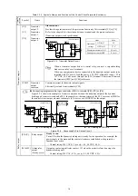
Table 2.2-5 Function of Each Slide Switch
Switch
Function
SW1
Switches the service mode of the digital input terminals between SINK and SOURCE.
▪
This switches the input mode of digital input terminals [X2] to [X7] to be used as the
SINK or SOURCE mode.
▪
Factory default: SINK
SW2, SW5
Reserved for particular manufacturers.
SW3, SW4, SW6, SW7, SW8
Not available.
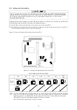
2.2.7 Fan power switching connector CN UX
If a power supply to be connected to auxiliary fan power input terminals [R1] and [T1] matches the specifications of the
following table, move the connector from the U1 to U2 position. In any other cases, retain the connector in the U1 position
(factory default).
Terminal rating: 660 to 690 VAC, 50/60 Hz, Maximum current 1.0 A
575 to 600 VAC, 50/60 Hz, Maximum current 1.0 A
Auxiliary power
printed circuit board
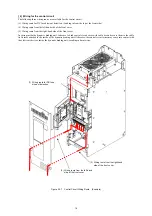
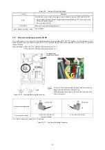
Figure 2.2-10 Inserting/Removing the connector
To remove the connector, pinch its upper side between your
fingers, unlock its fastener, and pull it up.
When mounting the connector, fit it over the connector until
it snaps into place.
19
Connector configuration
CN UX (red)
CN UX (red)
U2
U1
U2
U1
660 to 690 V, 50/60 Hz
(Factory default)
575 to 600 V, 50/60 Hz
Power source voltage
Note: Don’t connect the connector to U3 position.
Figure 2.2-11 Fan Power Switching Connector
Содержание BUC S-69D
Страница 8: ......


