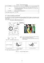
2.2.3 Basic Connections
(1) The grounding terminal must be grounded to prevent disasters such as electric shock and fire and reduce the noise.
(2) Use a reliable crimp terminal to connect each lead.
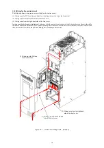
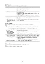
(3) After making connections (wiring), check that:
1) leads are correctly connected,
2) all necessary connections are made, and
3) no terminal or wire is short-circuited or grounded.
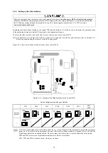
(4) When any connection is changed after the dynamic breaking unit is energized:
It takes a long time for the smoothing capacitor in the DC link circuit of the main circuit to be discharged after the power
supply is shut off. After the CHARGE lamp goes off, check with a multimeter or such that the DC voltage has been
reduced to a safe level (25V DC or less). Short-circuiting a circuit in which a voltage (potential) still remains may
generate sparks. Wait until the voltage goes away.
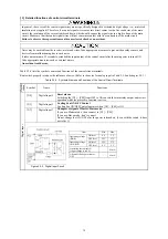
• Be sure to use wires in the specified size.
• Tighten terminals with specified torque.
Otherwise, a fire could occur.
.
• Be sure to ground the grounding terminals G.
Otherwise, an electric shock or fire could occur.
• Qualified electricians should carry out wiring.
• Be sure to perform wiring after shutting down the power.
Otherwise, electric shock could occur.
• Be sure to perform wiring after installing the dynamic breaking unit.
Otherwise, electric shock or injuries could occur.
2.2.4 Main circuit terminals
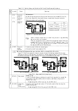
[ 1 ] Screw specifications and recommended wire sizes (main circuit terminals)
This section provides information on choices of wire sizes for main circuit.
Depending upon the main circuit wiring, electric noise could be applied to the control circuit, causing malfunctions.
Refer to the FRENIC-VG User's Manual (Stack type), Chapter 7 "EMC Compatible Peripherals," Appendix 5 "Proficient
Way to User Inverters (on Electric Noise), and Appendix 6 "Grounding As Noise Countermeasure and Ground Noise."
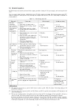
(1) Screw
specifications
Table 2.2-1 Screw Specifications
Inverter P(+)-N(-) line
connecting terminal
[P(+), N(-)]
External braking
resistor connecting
terminal
[DB1, DB2, DB3]
Type
Grounding terminals
[ G]
Auxiliary control
power input terminals
[R0, T0]
Auxiliary fan
power input terminals
[R1, T1]
Input terminals for fuse
blowout detection
[DCF1, DCF2]
BUC
S-69D
Screw
size
Tightening
torque
(N·m)
Screw
size
Tightening
torque
(N·m)
Screw
size
Tightening
torque
(N·m)
Screw
size
Tightening
torque
(N·m)
Screw
size
Tightening
torque
(N·m)
500
M12 48 M12 48 M12 48 M4 1.8 M3 0.5
(2) Recommended
wire
sizes
Table 2.2-2 Recommended Wire Sizes (Ambient temperature: 40°C)
11
Type
Inverter P(+)-N(-) line
connecting terminal
[P(+), N(-)] (mm
2
)
BUC
S-69D
When bus bar
is used
When wire
is used
External braking
resistor connecting
terminal
[DB1, DB2, DB3]
(mm
2
)
Grounding terminal
[ G]
(mm
2
)
Auxiliary control
power input terminals
[R0, T0]
Auxiliary fan
power input terminals
[R1, T1]
(mm
2
)
Input terminal for fuse
blowout detection
[DCF1, DCF2]
(mm
2
)
t4x50
500
100
38
38
2
1.25
(Note)
The recommended wire sizes listed above are for 1500 V MLFC insulated wires.
Содержание BUC S-69D
Страница 8: ......


