[ 3 ] Detailed functions of control circuit terminals
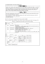
In general, the covers of the control signal wires are not specifically designed to withstand a high voltage (i.e., reinforced
insulation is not applied). Therefore, if a control signal wire comes into direct contact with a live conductor of the main
circuit, the insulation of the cover might break down, which would expose the signal wire to a high voltage of the main
circuit. Make sure that the control signal wires will not come into contact with live conductors of the main circuit.
Failure to observe these precautions could cause electric shock or an accident.
Noise may be emitted from the inverter, motor and wires. Take appropriate measures to prevent the nearby sensors and
devices from malfunctioning due to such noise.
It takes a maximum of 5 seconds to establish the input/output of the control circuit after the main power is turned ON.
Take appropriate measures, such as external timers.
An accident could occur.
Table 2.2-4 lists the symbols, names and functions of the control circuit terminals.
Route wires properly to reduce the influence of noise. (Refer to the notes for analog input in Table 2.2-4 and chapter 2.2.1.)
Table 2.2-4 Symbols, Names and Functions of the Control Circuit Terminals
Cla
ssifi-
cation
Symbol Name
Functions
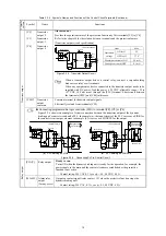
[X2]
Digital input 2
Reset alarm
Switching the [X2] – [CM] from OFF to ON cancels the alarm relay output and restart
operation while the protective function is active.
[X3]
Digital input 3
Cooling Fan ON/OFF Control
Cooling Fan ON/OFF Control operates when [X3] – [CM] is ON.
[X7]
Digital input 7
Changeover signal of Master/Slave mode.
If you use Master mode , then connect to [X7] – [CM].
If you use Slave mode , don’t connect.
Do not change the ON / OFF after the power is turned on. (Even with the switch, it does
not reflect.)
Digital input
Figure 2.2-2 Digital Input Circuit
Item Min.
Max.
ON level
0 V
2 V
Operating voltage
(SINK)
OFF level
22 V
27 V
ON level
22 V
27 V
Operating voltage
(SOURCE)
OFF level
0 V
2 V
Operating current at ON
(Input voltage is at 0 V)
4.5
mA
Allowable leakage current at
OFF
0.5
mA
13
Содержание BUC S-69D
Страница 8: ......


