


38
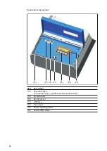
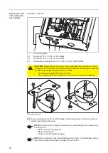
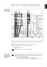
DC terminals
The white plastic divider that separates the AC from the DC connection area is not shown
in the figure.
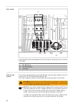
Solar module
ground
The inverter is equipped with a ground-fault detection and interruption (GFDI) circuit as re-
quired by UL 1741 and the National Electrical code.
The array’s negative conductor is connected to the grounding system in the inverter.
(1)
DC disconnect
(2)
DC terminal block
(3)
GFDI fuse
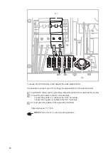
DC+
DC-
(2)
+
+
+
-
-
-
(1)
(3)
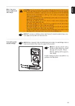
WARNING!
An electric shock can be fatal. Normally grounded conductors may
be ungrounded and energized when a ground fault is indicated. The ground fault
has to be repaired before operation is resumed
NOTE!
Do not connect the ground to the negative DC line at any point! This is al-
ready done within the inverter. If negative DC lines are connected to the DC ter-
minals or prior to this to the ground, this will circumvent the GFDI protection
system, preventing your inverter from properly detecting a fault current.
In addition, turning the DC disconnect to the OFF/open circuit condition will not
disconnect the array from ground, as it only disconnects the DC positive.
Содержание IG 2000
Страница 2: ...0...
Страница 4: ...2...
Страница 6: ...4...
Страница 10: ...8...
Страница 15: ...General Information...
Страница 16: ......
Страница 21: ...Installation and Startup...
Страница 22: ......
Страница 50: ...48...
Страница 51: ...Operation...
Страница 52: ......
Страница 80: ...78...
Страница 81: ...Troubleshooting and Maintenance...
Страница 82: ......
Страница 95: ...Appendix...
Страница 96: ......
Страница 113: ...111 EN US...
Страница 114: ...112...
Страница 115: ...113 EN US...


