


31
EN-US
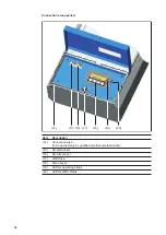
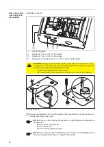
Monitoring the
Grid
Systems with
more than one in-
verter
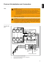
For larger photovoltaic systems, it is possible to connect several inverters in parallel with-
out any problems.
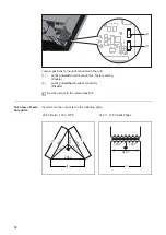
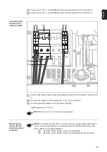
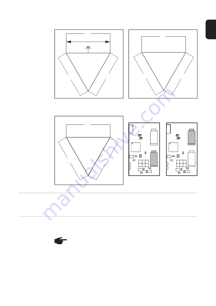
240 V Delta : 120 V Stinger
240 V Delta
208 V Delta
Jumper positions:
120 V
120 V
240 V
240 V
240 V
(1)
(2)
(2)
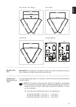
240 V
240 V
240 V
(2)
(2)
(2)
208 V
208 V
208 V
(2)
(2)
(2)
(1)
(2)
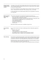
IMPORTANT!
The resistance in the leads to the AC-side connection terminals must be as
low as possible for optimal functioning of grid monitoring.
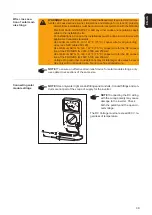
NOTE!
The inverters Fronius IG 2500-LV and Fronius IG 4500-LV are designed
to be connected to three-phase systems. Utilities generally allow up to 6 kVA of
unbalance, but check with your utility and try to balance the installation. Try to bal-
ance the installation.
The connection to the grid should be done in the following way:
-
Connect Fronius IG No. 1, No. 4, No. 7, ... to L1 and L2
-
Connect Fronius IG No. 2, No. 5, No. 8, ... to L2 and L3
-
Connect Fronius IG No. 3, No. 6, No. 9, ... to L1 and L3
Содержание IG 2000
Страница 2: ...0...
Страница 4: ...2...
Страница 6: ...4...
Страница 10: ...8...
Страница 15: ...General Information...
Страница 16: ......
Страница 21: ...Installation and Startup...
Страница 22: ......
Страница 50: ...48...
Страница 51: ...Operation...
Страница 52: ......
Страница 80: ...78...
Страница 81: ...Troubleshooting and Maintenance...
Страница 82: ......
Страница 95: ...Appendix...
Страница 96: ......
Страница 113: ...111 EN US...
Страница 114: ...112...
Страница 115: ...113 EN US...


