


27
EN-US
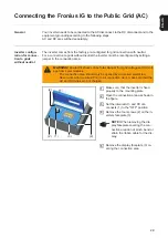
Fronius IG Installation
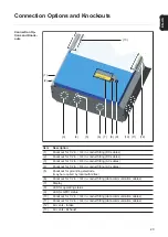
General
Recommended
screws for
mounting plate
assembly
In most cases, you should use 1/4 in. or 5/16 in. stainless steel or aluminum screws capa-
ble of supporting:
-
26 lbs. for Fronius IG 2000 / 3000 / 2500-LV
-
42 lbs. for Fronius IG 4000 / 5000 / 4500-LV
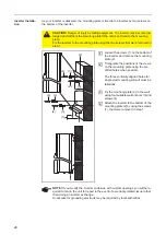
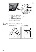
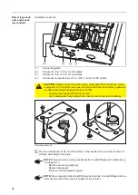
Attaching the
mounting plate -
mounting height
IMPORTANT!
Depending on the surface, different wall anchors and screws may be re-
quired for installing the wall bracket. These wall anchors and screws are not part of the
scope of delivery for the inverter. The installer is responsible for selecting the proper wall
anchors and screws.
NOTE!
The inverter is designed only for a vertical installation position.
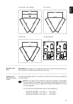
IMPORTANT!
Keep a minimum distance under the inverter corresponding to the ‘NEC
110.26 for code compliant disconnect location. If the DC disconnect is to be code compli-
ant, it must be readily accessible (NEC 690.14 (B) (1)).
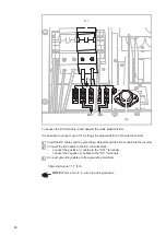
The DC disconnect is in the lower left part of the inverter. When choosing the inverter
mounting height, ensure a height that keeps the display slightly below eye level for best
possible readability of the display.
Содержание IG 2000
Страница 2: ...0...
Страница 4: ...2...
Страница 6: ...4...
Страница 10: ...8...
Страница 15: ...General Information...
Страница 16: ......
Страница 21: ...Installation and Startup...
Страница 22: ......
Страница 50: ...48...
Страница 51: ...Operation...
Страница 52: ......
Страница 80: ...78...
Страница 81: ...Troubleshooting and Maintenance...
Страница 82: ......
Страница 95: ...Appendix...
Страница 96: ......
Страница 113: ...111 EN US...
Страница 114: ...112...
Страница 115: ...113 EN US...


