14
WARNING
FIRE HAZARD
• DO NOT install flexible plastic or
flexible foil venting material.
• If installing semi-rigid venting, DO
NOT exceed 8 ft. (2.4 m) duct length.
In installations where the exhaust
system is not described in the charts,
the following method must be used
to determine if the exhaust system is
acceptable:
1.
Connect an inclined or digital
manometer between the dryer and
the point the
exhaust connects to the dryer.
2. Set the dryer timer and temperature
to air fluff (cool down) and start the
dryer.
3. Read the measurement on the
manometer.
4. The system backpressure MUST NOT
be higher than 0.6 inches of water
column. If the system back pressure
is less than 0.6 inches of water
column, the system is acceptable.
If the manometer reading is higher
than 0.6 inches of water column,
the system is too restrictive and the
installation is unacceptable.
Although vertical orientation of the
exhaust system is acceptable, certain
extenuating circumstances could affect
the performance of the dryer:
•
Only rigid metal duct work should be
used.
•
Venting vertically through a roof may
expose the exhaust system to down
drafts causing an increase in vent
restriction.
•
Running the exhaust system
through an uninsulated area may
cause condensation and faster
accumulation of lint.
•
Compression or crimping of the
exhaust system will cause an increase
in vent restriction.
•
The exhaust system should be
inspected and cleaned a minimum of
every 18 months with normal usage.
The more the dryer is used, the more
often you should check the exhaust
system and vent hood for proper
operation.
Correct
Incorrect
Install male fittings in correct direction:
WARNING
FIRE HAZARD
• Failure to follow safety warnings
exactly could result in serious injury,
death, or property damage.
• DO NOT install a booster fan in dryer
exhaust duct.
• Install all clothes dryers in
accordance with the installation
instructions in this manual.
PRE-INSTALLATION REQUIREMENTS
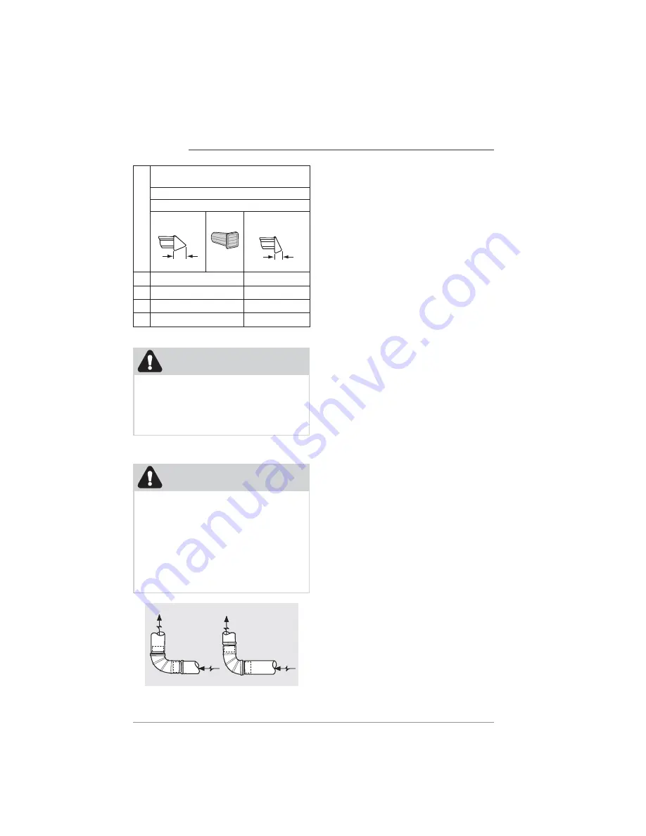
Max. Number of 90° turns
MAXIMUM LENGTH
of 4” (102 mm) Rigid Metal Duct
LONG VENT MODEL FLCE7523AW
VENT HOOD TYPE
4” (10.2 cm) louvered 2.5” (6.35 cm)
0
125 ft. (38 m)
93 ft. (28 m)
1
107 ft. (32 m)
75 ft. (22 m)
2
89 ft. (27 m)
58 ft. (17 m)
3
71 ft. (21 m)
40 ft. (12 m)


