96
PB
Wired Controller
FSWC1
Owner's Manual
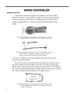
Fig. B: Schematic diagram of connection wire: Connect terminal
①
with wired
controller CN2; connect terminal
②
with the terminal
④
of patch cord
Only use the connection wire (fig. B) in the packing box of wired controller.
Connect the terminal
②
to the terminal
④
of patch cord which has been installed
on the air conditioner; insert terminal
①
to needle stand CN2 of wired controller.
If there’s protection terminal
③
, pull out the protection terminal at first and then
install it.
Use the connection wire and patch cord in the packing box of wired controller.
Pull out the protection terminal of patch cord at first, connect the connection wire
with the patch cord according to fig. D, and then insert the terminal
①
of connection
wire into the needle stand CN2 of wired controller and insert the terminal
⑤
of patch
cord into the terminal of wired controller of air conditioner as well.
25
Fig. C: Schematic diagram of patch cord: Terminal
③
is the protection terminal
;
connect terminal
④
to the terminal
②
of connection wire
;
connect
terminal
⑤
to the terminal of wired controller of air conditioner
Fig. D: Schematic diagram after the connection wire and the patch cord have
been connected: connect the terminal
②
of connection wire and the
terminal
④
of patch cord
If the air conditioner hasn’t been installed with the patch cord used for
connecting the wired controller.
WIRED CONTROLLER
Installation Instructions
Содержание FSHW091
Страница 8: ...8 INTRODUCTION FSHSW09A1A FSHSW12A1A Figure 102 Indoor Units FSHSW18A3A FSHSW24A3A FSHSW36A3A ...
Страница 47: ...47 INSTALLATION ...
Страница 48: ...48 INSTALLATION Installation Tools ...
Страница 72: ...72 WIRED CONTROLLER Display ...
Страница 122: ...122 TROUBLESHOOTING Malfunction of IDUFanMotorU8 Service Manual No Start End ...
Страница 146: ...146 WIRING DIAGRAMS Figure 8054 9 12KOutdoorUnitWiringDiagrams 60000706067401 3 2 N 1 C3 C4 ...
Страница 147: ...147 WIRING DIAGRAMS Figure 805 18 24kOutdoorUnitWiringDiagrams Figure 806 36kOutdoorUnitWiringDiagrams 6361000047001 ...
Страница 158: ...158 FIgure 906 PARTS CATALOG 9KOutdoorUnit 28 27 29 31 30 32 ...
Страница 160: ...160 PARTS CATALOG 12k OutdoorUnit 28 27 29 31 30 32 FIgure 907 ...

