34
PB
OPERATION
9-24k Sequence of Operation
(8)I feel control mode
After controller received I feel control signal and ambient temperature sent by remote controller, controller will work according to the ambient
temperature sent by remote controller.
(9)Compulsory defrosting function
(10)Refrigerant recovery function:
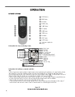
(1) Start up compulsory defrosting function
Under ON status, set heating mode with remote controller and adjust the temperature to 60.8
O
F. Press “+, -, +, -, +,-” button successively
within 5s and the complete unit will enter into compulsory defrosting status. Meanwhile, heating indicator on indoor unit will ON 10s and OFF
0.5s successively. (Note: If complete unit malfunctions or stops operation due to protection, compulsory defrosting function can be started
up after malfunction or protection is resumed.
(2) Exit compulsory defrosting mode
After compulsory defrosting is started up, the complete unit will exit defrosting operation according to the actual defrosting result, and the
complete unit will resume normal heating operation.
(11)Ambient temperature display control mode
(1) Enter refrigerant recycling function
Within 5min after energizing (unit ON or OFF status ), continuously press LIGHT button for 3 times within 3s to enter refrigerant
recycling mode; Fo is displayed and refrigerant recycling function is started. At this moment, the maintenance people closes liquid valve.
After 5min, stick the thimble of maintenance valve with a tool. If there is no refrigerant spraying out, close the gas valve immediately and
then turn off the unit to remove the connection pipe.
(2) Exit refrigerant recycling function
After entering refrigerant recycling mode, when receive any remote control signal or enter refrigerant recycling mode for 25min, the unit will
exit refrigerant recycling mode automatically If the unit is in standby mode before refrigerant recycling, it will be still in standby mode after
1. When user set the remote controller to display set temperature (corresponding remote control code: 01), current set temperature will be
displayed.
2. Only when remote control signal is switched to indoor ambient temperature display status (corresponding remote control code: 10) from
other display status (corresponding remote control code: 00, 01,11),controller will display indoor ambient temperature for 3s and then turn
back to display set temperature.
Under this mode, indoor fan operates at set fan speed. Compressor, outdoor fan, 4-way valve and electric heating tube stop operation.
Indoor fan can select to operate at high, medium, low or auto fan speed. Temperature setting range is 60.8~86.0
O
F.
(12)Off-peak energization function:
Adjust compressors minimum stop time. The original minimum stop time is 180s and then we change to:
The time interval between two start-ups of compressor can't be less than 180+T
s(0≤T≤15).
T is the variable of controller. Thats to say
the minimum stop time of compressor is 180s~195s.
(13) X-fan mode
When X-fan function is turned on, after turn off the unit, indoor fan will still operate at low speed for 2min and then the complete unit will be
turned off. When x-fan function is turned off, after turn off the unit, the complete unit will be turned off directly.
(14) 46º heating function
Under heating mode, you can set 46º heating function by remote controller. The system will operate at 46ºset temperature.
(15) Turbo fan control function
Set turbo function under cooling or heating mode to enter into turbo fan speed. Press fan speed button to cancel turbo wind.
No turbo function under auto, dry or fan mode.
Содержание FSHW091
Страница 8: ...8 INTRODUCTION FSHSW09A1A FSHSW12A1A Figure 102 Indoor Units FSHSW18A3A FSHSW24A3A FSHSW36A3A ...
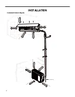
Страница 47: ...47 INSTALLATION ...
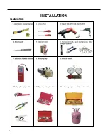
Страница 48: ...48 INSTALLATION Installation Tools ...
Страница 72: ...72 WIRED CONTROLLER Display ...
Страница 122: ...122 TROUBLESHOOTING Malfunction of IDUFanMotorU8 Service Manual No Start End ...
Страница 146: ...146 WIRING DIAGRAMS Figure 8054 9 12KOutdoorUnitWiringDiagrams 60000706067401 3 2 N 1 C3 C4 ...
Страница 147: ...147 WIRING DIAGRAMS Figure 805 18 24kOutdoorUnitWiringDiagrams Figure 806 36kOutdoorUnitWiringDiagrams 6361000047001 ...
Страница 158: ...158 FIgure 906 PARTS CATALOG 9KOutdoorUnit 28 27 29 31 30 32 ...
Страница 160: ...160 PARTS CATALOG 12k OutdoorUnit 28 27 29 31 30 32 FIgure 907 ...

