


123
PB
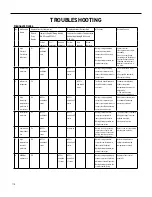
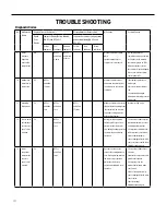
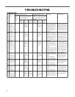
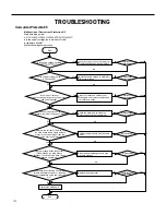
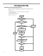
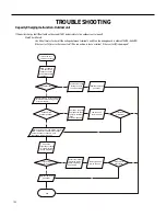
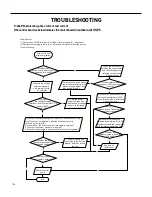
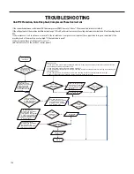
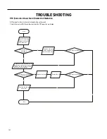
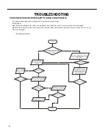
TROUBLESHOOTING
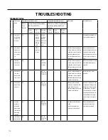
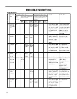
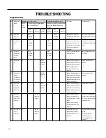
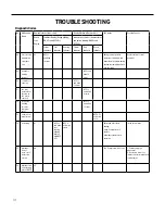
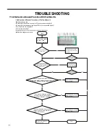
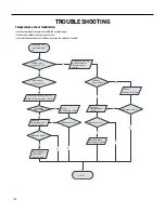
Overcurrent Protection E5
Malfunction of Overcurrent Protection E5
Main detection points:
Start
●
Is the supply voltage too low with overload?
●
Hardware trouble?
Malfunction diagnosis process:
Is the supply voltage unstable
of the rated voltage on the nameplate
Adjust the supply voltage to maintain it
within normal range
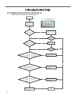
Clean the indoor and outdoor heat
exchangers and remove the blockage
of air inlet and outlet
Check the motor and reinstall the
motor to have the fan run normally
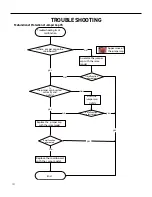
Replace the mainboard with the same
model
Flush the heat exchangers with high
pressure nitrogen
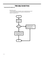
Replace the compressor
End
Replace the mainboard
with the same model
Is the supply voltage too low
with overload?
Is the indoor / outdoor
heat exchanger dirty,or are the air inlet
and outlet blocked?
The fan is abnormal? Fan
speed is too low or fan doesn’t rotate
Measure the current of live wire on
the main board with a clamp ampere
meter. Is the current higher than the
value of the overcurrent protection?
Is there blockage inside the system?
(Filth blockage, ice plug, greasy
blockage, the cut off valve hasn’t been
opened completely)
Is malfunction
eliminated
Is the compressor running abnormally?
Is there abnormal sound or oil leakage;
Is the temperature of the shell too high,
etc.?
Is malfunction
eliminated
Is malfunction
eliminated
Is malfunction
eliminated
Is malfunction
eliminated
Is malfunction
eliminated
Is malfunction
eliminated
Yes
Yes
Yes
Yes
Yes
Yes
Yes
Yes
Yes
Yes
Yes
Yes
Yes
Yes
No
No
No
No
No
No
No
No
No
No
No
No
No
Содержание FSHW091
Страница 8: ...8 INTRODUCTION FSHSW09A1A FSHSW12A1A Figure 102 Indoor Units FSHSW18A3A FSHSW24A3A FSHSW36A3A ...
Страница 47: ...47 INSTALLATION ...
Страница 48: ...48 INSTALLATION Installation Tools ...
Страница 72: ...72 WIRED CONTROLLER Display ...
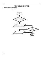
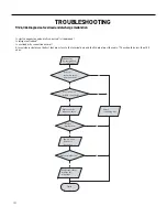
Страница 122: ...122 TROUBLESHOOTING Malfunction of IDUFanMotorU8 Service Manual No Start End ...
Страница 146: ...146 WIRING DIAGRAMS Figure 8054 9 12KOutdoorUnitWiringDiagrams 60000706067401 3 2 N 1 C3 C4 ...
Страница 147: ...147 WIRING DIAGRAMS Figure 805 18 24kOutdoorUnitWiringDiagrams Figure 806 36kOutdoorUnitWiringDiagrams 6361000047001 ...
Страница 158: ...158 FIgure 906 PARTS CATALOG 9KOutdoorUnit 28 27 29 31 30 32 ...
Страница 160: ...160 PARTS CATALOG 12k OutdoorUnit 28 27 29 31 30 32 FIgure 907 ...


