background image

55

PB

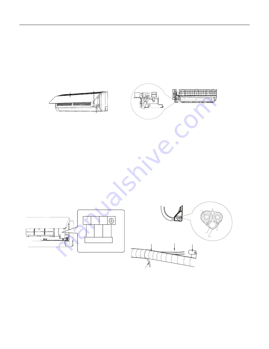
Connect Wire of Indoor Unit
 

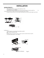
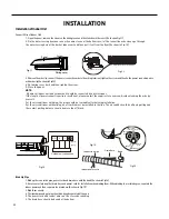
1.  Open the panel, remove the screw on the wiring cover and then take down the cover.(As show in Fig.11) 

 2. 

Fix the wire crossing board on connection wire sleeve at the bottom case; let the connection wire sleeve go through  


the wire crossing hole at the back of indoor unit, and then pull it out from the front.(As show in Fig.12)

INSTALLATION

Installation of Indoor Unit

Fig.11

Wiring cover

Screw

Panel

connection wire sleeve

Fig.12


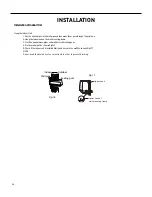
3. Remove the wire clip; connect the power connection wire to the wiring terminal; tighten the screw and then fix the power connection wire  


with wire clip.(As show in Fig.13)


4. Put wiring cover back and then tighten the screw.


5. Close the panel.

 NOTE: 


 All wires of indoor unit and outdoor unit should be connected by a professional.


If the length of power connection wire is insufficient, please contact the supplier for a new one. Avoid extending the wire by  

 yourself.


For the air conditioner with plug, the plug should be reachable after finishing installation.


For the air conditioner without plug, an air switch must be installed in the line. The air switch should be all‑pole parting and  


the contact parting distance should be more than 1/8inch.

N(1)

2

3

yellow-

green

Outdoor unit connection

Fig.13

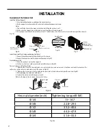
Indoor unit

Gas
pipe

Indoor and

outdoor power cord

Liquid 

pipe

Drain hose

Band

Connection pipe

Indoor power cord

Drain hose

Band

Fig.14

Fig.15

Bind Up Pipe


1. Bind up the connection pipe, power cord and drain hose with the band.(As show in Fig.14)


2. Reserve a certain length of drain hose and power cord for installation when binding them. When binding to a certain degree, separate the  


indoor power and then separate the drain hose.(As show in Fig.15)


3. Bind them evenly.


4. The liquid pipe and gas pipe should be bound separately at the end.


5. The power cord and control wire can’t be crossed or winding.


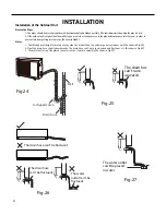
6. The drain hose should be bound at the bottom.

Содержание FSHW091

Страница 1: ...Manual Floating Air Select 96621400_00 FSHW091 9 000 BTU Single Zone 110V FSHW121 12 000 BTU Single Zone 110V FSHW183 18 000 BTU Single Zone 230V FSHW243 24 000 BTU Single Zone 230V FSHW363 36 000 BTU Single Zone 230V ...

Страница 2: ... Selection of Installation Location 51 Installation of Indoor Unit 53 Leak Check Evacuation and Charging Triple Evacuation 60 Checklist and Operation Test 62 Check Unit following Installation 62 Test Operation 62 REMOVAL 63 Indoor Unit 63 Outdoor Unit 68 WIRED CONTROLLER 72 Display 72 Buttons 74 Operation Instructions 75 Installation Instructions 93 R 410A SEALED SYSTEM REPAIR 98 Service Valves Ap...

Страница 3: ...erload Protection Diagnosis 136 PFC Correction Power Factor Outdor Unit Malfuction 137 Communication malfunction following AP1 for outdoor unit control board 138 High pressure Protection 139 Troubleshooting for Malfunction without Active Error Code 140 WIRING DIAGRAMS 143 9 12K Indoor Unit Wiring Diagram 143 18 24k Indoor Unit Wiring Diagram 144 36K Indoor Unit Wiring Diagrams 145 18 24k Outdoor U...

Страница 4: ...this manual and on your appliance Always read and obey all safety messages This is a safety Alert symbol This symbol alerts you to potential hazards that can kill or hurt you and others All safety messages will follow the safety alert symbol with the word WARNING or CAUTION These words mean Indicates a hazard which if not avoided can result in severe personal injury or death and damage to product ...

Страница 5: ...property damage personal injury and or death Your safety and the safety of others are very important We have provided many important safety messages in this manual and on your appliance Always read and obey all safety messages This is the safety Alert symbol This symbol alerts you to potential hazards that can kill or hurt you and others All safety messages will follow the safety alert symbol with...

Страница 6: ... Handle discharge and test capacitors according to safe established standards and approved procedures Extreme care proper judgment and safety procedures must be exercised if it becomes necessary to test or troubleshoot equipment with the power turned on to the unit Do not spray water on the air conditioning unit while the power is on Electrical component malfunction caused by water could result in...

Страница 7: ... Insider C Cassette R Remote Condenser Function HS H eat Pump Single HM Heat Pump Multi HF Heat Pump Flex Single and Multizone Cooling BTU HR Model Approximate Introductory Chara cter Voltage A 2019 B 202 0 C 2021 D 2022 1 115 Volts 3 230 Volts MODEL IDENTIFICATION GUIDE Marketing Suffix Letter indicates modification to existing model Figure 101 Model Identification Guide ...

Страница 8: ...8 INTRODUCTION FSHSW09A1A FSHSW12A1A Figure 102 Indoor Units FSHSW18A3A FSHSW24A3A FSHSW36A3A ...

Страница 9: ...9 INTRODUCTION FSHSR09A1A FSHSR12A1A FSHSR18A3A FSHSR24A3A FSHSR36A3A Figure 103 Outdoor Units FSHSW09A1A FSHSW12A1A FSHSW18A3A FSHSW24A3A FSHSW36A3A Figure 104 Remote Control ...

Страница 10: ...72 24000 35996 6 HeatingCapacity W 2784 3810 5803 7034 10140 HeatingCapacity Btu h 9500 13000 19800 24000 34600 Min HeatingCapacity W 610 1000 1000 2500 4390 Min HeatingCapacity Btu h 2081 3412 3412 8600 14978 68 Max HeatingCapacity W 3600 4400 6400 7600 10550 Max HeatingCapacity Btu h 12283 15013 21837 26000 35996 6 CoolingPowerInput W 900 1194 1820 2010 4100 Min CoolingPowerInput W 350 380 80 60...

Страница 11: ...W 20 20 35 30 70 Fan Motor RLA A 0 24 0 25 0 37 0 32 0 4 Fan Motor Capacitor μF 4 4 2 5 3 0 Evaporator Form Aluminum Fin copper Tube Aluminum Fin copper Tube Aluminum Fin copper Tube Aluminum Fin copper Tube Aluminum Fin copper Tube Evaporator Pipe Diameter inch 0 197 0 197 2 7 Evaporator Row fin Gap inch 2 1 18 2 1 18 2 1 18 Evaporator Coil Length L D W inch 23 7 8 10 8 16 25 7 8 12 1 16 33 1 4 1...

Страница 12: ...PC115 95U1 1NT11L 6233 or KSD115 or HPC115 95U1 1NT11L 6233 Fan Type Axial flow Axial flow Axial flow Axial flow Axial flow Fan Diameter inch 15 748 15 748 20 21 654 Fan Motor Speed rpm 850 900 800 800 890 Fan Motor Power Output W 30 30 60 60 170 Fan Motor RLA A 0 24 0 23 0 52 0 4 0 73 Outdoor Unit Air Flow Volume m3 h 1800 1800 3200 3200 4400 Condenser Form Aluminum Fin copper Tube Aluminum Fin c...

Страница 13: ...e FrigdZone TemperateZone Isolation I I I I I MoistureProtection IPX4 IPX4 IPX4 IPX4 IPX4 SoundPressure Level dB A 52 53 57 58 65 SoundPowerLevel dB A 62 63 67 68 75 Dimension W H D inch 33 386 21 26 12 598 33 386 21 26 12 598 37 6 27 6 15 6 37 598 27 559 15 591 38 583 31 102 16 811 NetWeight lb 62 8 67 3 97 103 635 160 965 GrossWeight lb 68 4 72 8 106 9 113 558 171 99 Refrigerant R410A R410A R410...

Страница 14: ...the operating ambient temperature of outdoorunit This data is obtained with Free Spin of the Condenser and not in a testing mode Conditions Capacities and selection data 1 Pipelength height difference 25ft 7 6m 0 ft 0m 2 Compressor at ratedinverter frequency 3 Indoor fan speedat high fan speed 4 Capacity loss due to frost accumulation and defrost operationisnot included ...

Страница 15: ... 0 86 6 96 5 12 0 88 7 20 5 29 0 90 6 60 4 85 0 91 23 5 58 4 13 0 83 6 54 4 84 0 87 6 96 5 15 0 89 7 44 5 51 0 92 7 68 5 68 0 93 7 08 5 24 0 94 32 5 82 4 34 0 86 6 78 5 05 0 91 7 20 5 36 0 93 7 68 5 72 0 96 7 92 5 90 0 97 7 32 5 45 0 98 41 6 54 4 91 0 89 7 50 5 63 0 94 7 92 5 94 0 96 8 40 6 30 0 99 8 64 6 48 1 00 8 04 6 03 1 01 50 7 26 5 48 0 93 8 22 6 21 0 98 8 64 6 52 1 00 9 12 6 89 1 03 9 36 7 ...

Страница 16: ...9 46 6 95 1 25 11 22 8 25 1 32 12 98 9 54 1 38 13 42 9 86 1 46 13 86 10 19 1 50 23 8 36 6 19 1 13 9 90 7 33 1 32 11 66 8 63 1 39 13 42 9 93 1 46 14 08 10 42 1 48 14 74 10 91 1 56 32 9 02 6 72 1 21 10 34 7 70 1 37 12 10 9 01 1 44 13 86 10 33 1 52 14 74 10 98 1 58 15 40 11 47 1 62 41 9 68 7 26 1 27 11 66 8 75 1 41 13 42 10 07 1 48 15 18 11 39 1 56 15 84 11 88 1 64 16 50 12 38 1 68 50 10 78 8 14 1 33...

Страница 17: ... 80 3 76 36 60 28 50 3 83 104 19 80 15 50 3 47 24 50 19 20 3 59 27 20 21 40 3 78 29 90 23 50 3 98 33 30 26 10 4 09 33 90 26 60 4 20 115 16 10 12 70 3 72 22 50 17 80 3 82 25 20 19 90 4 02 27 90 22 00 4 23 30 60 24 20 4 38 30 90 24 40 4 42 Heating Template TC PI TC PI TC PI TC PI TC PI kBtu h kW kBtu h kW kBtu h kW kBtu h kW kBtu h kW 15 17 12 80 2 73 13 50 2 78 14 20 2 84 14 90 2 90 16 30 3 02 5 7 ...

Страница 18: ...Compressor frequency Hz Pipe lengt 24 6ft Conditions Pipe lengt 24 6ft Indoor DB70 F WB60 F Outdoor DB19 94 F WB19 04 F Indoor air flow High Cooling Heating Cooling Heating 0 0 1 0 2 30 0 4 0 5 0 6 0 7 0 9 80 11 10 9 8 7 6 5 4 3 10 0 20 30 40 50 60 70 80 90 100 110 120 2 1 0 Compressor speed rps Current A 11 10 9 8 7 6 5 4 3 2 1 0 Compressor speed rps Current A 24K 24K 18K 18K Outdoor DB95 F Indoo...

Страница 19: ...12 14 0 0 2 00 1 120 0 2 4 6 8 10 12 14 0 0 2 100 120 Condition Indoor DB 80 F WB66 F Indoor air flow Super High Pipe length 24 39 64ft Condition Indoor DB 70 F Indoor air flow Super High Pipe length 24 39 64ft Current A 40 60 80 Compressor Frequency Hz Current A 40 60 80 Compressor Frequency Hz ...

Страница 20: ...5 F flow Super High Indoor air Indoor DB80 F WB66 9 F Pipe length 24 6ft Conditions Outdoor DB19 94 F WB19 04 F Indoor DB70 F air flow Super Indoor High Pipe length 24 6ft Cooling 4 5 4 1 110 100 90 80 70 60 50 40 23 32 41 50 Outdoor temp F Capacity ratio 100 105 95 90 85 80 75 70 65 60 55 50 Capacity ratio Outdoor DB95 F Indoor air flow Super High Conditions Indoor DB80 F WB66 9 F 89 6 91 4 93 2 ...

Страница 21: ... Indoor DB 80 F WB66 F Indoor air flow Super High Pipe length 24 39 64ft 110 100 90 80 70 60 50 40 23 32 41 50 Conditions High Indoor air length Pipe Indoor DB70 F flow Super 24 39 64ft Indoor side noise when blowing Outdoor side noise when blowing Indoor fan motor rotating speed Noise dB A 40 50 60 70 Compressor frequency Hz 50 60 30 40 20 Super High Low Middle High 40 42 44 46 48 50 52 54 56 20 ...

Страница 22: ...46 48 50 52 54 56 58 60 20 30 40 50 60 70 80 90 100 Compressor frequency Hz Noise dB A Heating Cooling Indoor side noise Outdoor side noise 30 40 50 60 L 36K 30K 30K H S Noise dB A M H Indoor fan motor rating speed 45 50 55 60 65 70 75 80 20 30 40 50 60 70 80 90 100 Compressor frequency Hz Noise dB A Indoor side noise Outdoor side noise 36K ...

Страница 23: ...enser P Pressure at the side of big valve Connection pipe length 24 6ft SPECIFICATIONS RatedHeating connecting indoorand DB WB Model Pressure ofgaspipe connecting indoorand outdoorunit Inletandoutletpipetempera tureofheatexchanger Fanspeedof indoorunit Fanspeed ofoutdoor unit Compressor frequency Hz Indoor Outdoor PSI T1 oF T2 oF 70 60 19 94 19 04 9k 362 32 405 80 in 167 181 4 out 98 6 113 in 33 8...

Страница 24: ...IndoorUnitDimensions W D H Models W H D 09K 31 1 8 10 13 16 7 7 8 12K 33 1 4 11 3 8 8 1 4 12K 09K 3 9 16 5 7 8 1 8 2 6 5 8 18 1 4 6 1 4 2 Φ 3 16 Φ2 3 16 2 1 8 1 5 16 2 4 7 8 7 1 16 4 15 16 3 1 4 1 3 8 Φ2 3 16 2 3 16 Φ 1 3 8 Unit inches ...

Страница 25: ...doorUnitDimensions SPECIFICATIONS W D H 4 7 2 3 16 7 5 1 2 7 1 2 1 1 2 Φ2 3 16 Φ2 3 16 3 1 8 6 1 11 16 8 1 8 27 7 5 16 Φ2 3 4 Φ2 3 4 18K 24K Models W H D 18K 38 3 16 11 13 16 8 13 16 24K 42 7 16 12 13 16 9 11 16 Unit inches ...

Страница 26: ...NS Figure 227 9 12KOutdoorUnitDimensions Figure 226 36KindoorUnitDimensions 53 9 64 12 53 64 10 11 19 32 3 1 2 1 37 64 13 25 32 10 29 3 8 Φ2 3 4 Φ2 3 4 Unit inches 21 1 4 11 1 4 30 10 12 5 8 33 3 8 21 1 4 Unit inches ...

Страница 27: ...SPECIFICATIONS Figure 228 18 24KOutdoorUnitDimensions Figure 229 36KOutdoorUnitDimensions Unit inches 35 13 3 8 27 9 16 15 5 8 38 14 5 16 22 14 37 64 31 7 64 16 13 16 15 9 16 39 1 2 24 36 7 32 Unit inches ...

Страница 28: ...e remote controller it could be used for the air conditioners with multifunction For some function which the model doesn t have if press the corresponding button on the remote controller that the unit will keep the original running status After putting through the power the air conditioner will give out a sound Operation indicator is ON red indicator the colour is different for different models Af...

Страница 29: ... this button can set fan speed circularly as auto AUTO low medium high 1 ON OFF button Press this button to turn on the unit Press this button again to turn off the unit 2 MODE button Press this button to select your required operation mode FAN AUTO COOL DRY HEAT 5 TURBO button Under COOL or HEAT mode press this button to turn to quick COOL or quick HEAT mode icon is displayed on remote controller...

Страница 30: ...time Press TIMER ON to icon resumes displaying Cancel TIMER ON Under the condition that TIMER ON is started up press TIMER ON button to cancel it TIMER OFF button TIMER OFF button can set the time for timer off After pressing this button icon disappears and the word OFF on remote controller blinks Press or button to adjust TIMER OFF setting After each pressing or button TIMER OFF setting will incr...

Страница 31: ...ing function set temperature can t be adjusted Press TURBO button and the remote controller won t send signal Sleep function and 46ºF heating function can t operate at the same time If 46ºFheating function has been set under cooling mode press sleep button will cancel 46ºF heating function If sleep function has been set under cooling mode start up the 46ºF heating function will cancel sleep functi...

Страница 32: ... Press SWING button to select fan blowing angle 1 Press the back side of remote controller marked with The distance between signal sender and receiving window should be no more than 8m and there should be no obstacles between them indoor unit during operation Replace new batteries of the same model when replacement is required If you won t use remote controller for a long time please take out the ...

Страница 33: ...n function 3 Display Set temperature is the set value under each condition Ambient temperature is Tamb Tcompensation for heat pump unit and Tamb for cooling only unit 4 If there s I feel function Tcompensation is 0 Others are same as above 5 Fan mode Under this mode indoor fan operates at set fan speed Compressor outdoor fan 4 way valve and electric heating tube stop operation Indoor fan can selec...

Страница 34: ...e any remote control signal or enter refrigerant recycling mode for 25min the unit will exit refrigerant recycling mode automatically If the unit is in standby mode before refrigerant recycling it will be still in standby mode after 1 When user set the remote controller to display set temperature corresponding remote control code 01 current set temperature will be displayed 2 Only when remote cont...

Страница 35: ...ame as the cooling mode 2 The temperature setting range is 61 86ºF 3 Air supplying Mode 1 If Toutdoor ambient temperature Tlow temperature cooling temperature the temperature can be set at 61 86ºF Cooling at room temperature 2 If Toutdoor ambient temperature Tlow temperature cooling temperature the temperature can be set at 77 86ºF Cooling at low temperature that is the minimum setting temperature...

Страница 36: ...gic 1 Compressor Control Start the compressor after starting cooling heating dehumidifying operations and the outer fans start for 5s When the machine is shutdown in safety stops and when switching to air supplying mode the compressor will stop immediately In all modes once the compressor starts up it will not be allowed to stop until having run for the tmin compressor running time Note including ...

Страница 37: ... is 35 6ºF the machine is allowed to start otherwise it should not be started and should be stopped to treat according to the overload protection Clear the trouble at the mode of power turn off heating and the protection times are not counted 1 Starting estimation After the compressor stopped working for 180s if Touter pipe TCooling overload frequency limited temperature the temperature of hystere...

Страница 38: ...ature at normal speed during discharging you should limit the frequency raising of compressor 3 Reducing frequency at normal speed and stopping machine If Tfrequency reducing temperature at normal speed during discharging TDischarge Tfrequency reducing temperature at high speed during discharging you should adjust the compressor frequency by reducing 8Hz 90s till the lower limit After it was runni...

Страница 39: ...ule Tfrequency reducing temperature at normal speed of module you should limit the frequency raising of compressor 3 Reducing frequency at normal speed and power turn off If Tfrequency reducing temperature at normal speed of module TModule Tfrequency reducing temperature at high speed of module you should adjust the compressor frequency by reducing 8Hz 90s till the lower limit After it was running...

Страница 40: ...of PFC immediately under the condition of PFC protection it should turn off the PFC and compressor at the same time 2 It shows the failure is cleared out if PFC Protection stopped working 3 min and recovers to run automatically 3 If the PFC protection failure occurs 3 times consecutively it will be available if you press ON OFF and clear the PFC Protection times when start up PFC for 10min 4 Modul...

Страница 41: ...e electric heating of chassis will stop operation 3 When 32ºF Toutdoor amb 35 6ºF the electric heating of chassis will keep original status 1 When Toutdoor amb 23ºF compressor stops operation while the electric heating of compressor starts operation 2 When Toutdoor amb 28 4ºF the electric heating of compressor stops operation 3 When 23ºF Toutdoor amb 28 4ºF the electric heating of compressor will ...

Страница 42: ... at least 3 minutes the compressor will resume its original operation state Total current up and frequency down protection If Itotal 16A frequency rise will be allowed if Itotal 17A frequency rise will not be allowed if Itotal 18A the compressor will run at reduced frequency and if Itotal 20A the compressor will stop and the outdoor fan will stop with a time lag of 60s 2 Dehumidifying Mode Working...

Страница 43: ...or amb 75 F if Ttube 108 F the indoor fan will run at low speed and after one minute the indoor fan will be converted to preset speed Within 1 minute low speed operation if Ttube 104 F the indoor fan will be converted to preset speed Note Tindoor amb indicated in and refers to under initially heating mode the indoor ambient temperature before the command to start the compressor is performed accord...

Страница 44: ...ssive 30 seconds Overload After the compressor has operated for 3 minutes the sensor is detected to be open circuited or short circuited for successive 30 seconds Exhaust temperature protection of compressor If exhaust temperature 208 F frequency is not allowed to rise If exhaust temperature 217 F the compressor will run at reduced frequency If exhaust temperature 230 F the compressor will stop If...

Страница 45: ...Heat evaporator Valve condenser exchanger Valve side Liquid pipe Gas pipe side Accumlator Compressor Strainer Electron Strainer expansion valve Indoor unit COOLING HEATING Discharge Outdoor unit Suction 4 Way valve Heat exchanger evaporator Heat exchanger condenser Valve Valve side Liquid pipe Gas pipe side Strainer Strainer Capillary Accumlator Electron expansion Compressor valve ...

Страница 46: ...gram COOLING HEATING 4 Way valve Discharge Suction Heat exchanger evaporator Heat exchanger condenser Valve Valve side Liquid pipe Gas pipe side Electron Strainer expansion valve Strainer Accumlator Compressor Liquid pipe 1 4 inch Gas pipe 5 8 inch ...

Страница 47: ...47 INSTALLATION ...

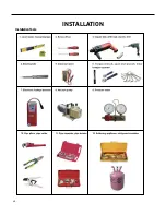
Страница 48: ...48 INSTALLATION Installation Tools ...

Страница 49: ...4 inches Space to the wall S p a c e t o t h e o b s t r u c t i o n r o o l f e h t o t e c a p S A t l e a s t 6 0 i n c h e s Space to the obstructio At least 28 inches At least Space to the wall 12 inches At least 24 inches Space to the obstruction Atleast12inches Drainage pipe Space to the obstruction At least 24 inches Space to the obstruction ...

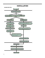
Страница 50: ...onnect wires of outdoor unit Bind up pipes and hang the indoor unit Make the bound pipes pass through the wall hole and then connect outdoor unit Neaten the pipes Vacuum pumping and leakage detection Check after installation and test operation Finish installation Select outdoor unit installation location Install the support of outdoor unit select it according to the actual situation Connect pipes ...

Страница 51: ...explosivegas orvolatileobjectsspreadintheair 2 Places withhigh frequency devices suchasweldingmachine medicalequipment 3 Places withoilor fumes inthe air 4 Places withsulfureted gas IndoorUnit 1 There should be no obstructionnearairinletandairoutlet 2 Selectalocationwhere the condensationwatercanbedispersedeasilyandwon taffectotherpeople 3 Selectalocationwhichis convenienttoconnecttheoutdoorunitan...

Страница 52: ... electricity and safety 6 Do not put through the power before finishing installation 7 For appliances with type Y attachment the instructions shall contain the substance of thefollowing If the supply cord is damaged it must be replaced by the manufacturer its service agent or similarly qualified persons in order to avoid a hazard 8 The temperature of refrigerant circuit will be high please keep the ...

Страница 53: ... piping hole with the diameter of 2 3 4inch on the selected outlet pipe position In order to drain smoothly slant the piping hole on the wall slightly downward to the outdoor side with the gradient of 5 10 As show in Fig 2 Note 1 Pay attention to dust prevention and take relevant safety measures when opening the hole 2 The plastic expansion particles are not provided and should be bought locally F...

Страница 54: ...As show in Fig 7 Insulating pipe Torque wrench Open end wrench Indoor pipe Pipe Union nut Pipe joint Union nut Pipe Refer to the following table for wrench moment of force Fig 5 Fig 6 Fig 7 Hex nut diameter inch Tightening torque ft Ibf Φ1 4 11 14 7 Φ3 8 22 8 29 5 Φ1 2 33 2 40 6 Φ5 8 44 3 47 9 Φ3 4 51 6 55 3 Install Drain Hose 1 Connect the drainhose to the outletpipe of indoorunit AsshowinFig 8 2...

Страница 55: ...ase contact the supplier for a new one Avoid extending the wire by yourself For the air conditioner with plug the plug should be reachable after finishing installation For the air conditioner without plug an air switch must be installed in the line The air switch should be all pole parting and the contact parting distance should be more than 1 8inch N 1 2 3 yellow green Outdoor unit connection Fig ...

Страница 56: ...he wall mounting frame 3 Stuffthegap betweenpipes and wallhole withsealinggum 4 Fixthe wallpipe As show inFig 16 5 Check ifthe indoor unitis installed firmly and closedtothewall AsshowinFig 17 NOTE Do not bend the drain hose too excessively in order to prevent blocking Indoor Outdoor Wall pipe Sealing gum Upper hook Lower hook of wall mounting frame Fig 16 Fig 17 ...

Страница 57: ...nd Heating UnitOnly 1 Connect the outdoor drainjointinto the hole onthechassis 2 Connect the drainhose into the drainvent As showinFig 19 Fixthe OutdoorUnit 1 Place the outdoor unit on the support 2 Fix the foot holes of outdoor unit with bolts As show in Fig 20 Connect Indoor and Outdoor Pipes 1 Remove the screw on the right cable cross plate sub assy and valve cover of outdoor unit and then remo...

Страница 58: ...le cross plate sub assy Notes 1 After tightening the screw pull the power cord slightly to check if it is firm 2 Never cut the power connection wire to prolong or shorten the distance 3 The connecting wire and connection pipe cannnot touch each other 4 Top cover of outdoor unit and electric box assembly should be fixed by the screw Otherwise it can cause a fire or short circuit caused by water or dus...

Страница 59: ... The through wall height of drain hose shouldn t be higher than the outlet pipe hole of indoor unit As show in Fig 25 2 Slant the drain hose slightly downwards The drain hose can t be curved raised and fluctuant etc As show in Fig 26 3 The water outlet can t be placed in water in order to drain smoothly As show in Fig 27 The drain hos can t raise upwards Fig 24 Fig 25 U shaped curve Wall Drain hose...

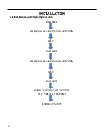
Страница 60: ...he valve to the vacuum pump and check for micron rise for 15 minutes If microns rise to near atmospheric pressure there is a potential leak follow Section 8 7 A If microns rise over 5000 the system is very wet and will require further nitrogen purges 3 2nd Nitrogen Break Once the system holds below 5000 microns reconnect the nitrogen tank break the system vacuum with 30 50psi of nitrogen Wait 5 mi...

Страница 61: ...ON Leak Check Evacuation andCharging TripleEvacuation WAIT EVACUATE BREAK VACUUM WITH DRY NITROGEN CHARGE SYSTEM EVACUATE WAIT EVACUATE CHECK FOR TIGHT DRY SYSTEM IF IT HOLDS A VACUUM BREAK VACUUM WITH DRY NITROGEN ...

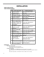
Страница 62: ...akage Is the unit grounded securely 8 Does the wiring follow the specifications 9 It may cause malfunction or damage the parts Is there any obstruction in air inlet and air outlet 10 It may cause insufficient cooling heating 11 It may cause malfunction or damaging the parts Dust and debris not after installation removed after The gas valve and liquid valve of connection pipe are open completely It...

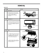
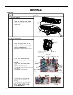
Страница 63: ...l louver from the crankshaft of step motor to remove it the groove on the front panel respectively that are locking the display board 1 A1 display Screw off the 2 screws that are locking the display board Separate the display board from the front panel 2 A3 A5 display Screw off the 2 screws 3 Remove panel Separate the panel rotation shaft from removes the front panel Panel Screws Screws Screws A1 ...

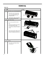
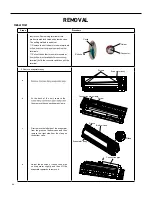
Страница 64: ...ttom case Front case sub assy Display Screws Clasp Screw caps Loosen the connection clasps between front case sub assy and bottom case Lift up the front case sub assy and take it out Screws Screw Detecting plate WIFI 2 Procedure Step 4 Remove electric box cover 2 and detecting plate WIFI Remove the screws on the electric box cover 2 and detecting plate WIFI then remove the electric box cover 2 and...

Страница 65: ...ox assy Electric box Twist off the screws that are locking each lead wire and rotate the electric box assy Twist off the screws that are locking the wire clip Loosen the power cord and remove it s wiring terminal Lift up the main board and take it off Electric box assy Clasps Shield cover of electric box sub assy Cold plasma generator Water retaining sheet Grounding screw Screw Power cord Wire cli...

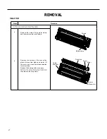
Страница 66: ...heath Remove the soft sheath for some terminals terminals Pull out the holder for some terminals at terminal hold the connector and then pull the terminal Holder Connector Procedure Steps 9 Remove evaporator assy Screws Connection pipe clamp Evaporator assy Evaporator assy Screw Groove Bottom case Clasp Connection pipe At the back of the unit remove the then remove the connection pipe clamp Adjust...

Страница 67: ... remove the motor clamp Screws Screw Motor clamp Motor Holder sub assy Step motor Remove the screws at the connection place of cross flow blade and motor lift the motor and cross flow blade upwards to remove them Remove the bearing holder sub assy then remove the step motor Screws a b ...

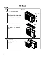
Страница 68: ...move the cable cross plate sub assy Remove the screws fixing valve cover and then remove the valve cover top cover cable cross plate sub assy valve cover front grille Remove connection screws connecting the top cover plate with the front panel and the right side plate and then remove the top cover Remove connection screws between the front grille and the front panel Then remove the front grille ...

Страница 69: ...ow blade Steps Remove connection screws connecting the front panel with the chassis and the motor support and then remove the front panel front panel right side plate Remove connection screws connecting the right side plate with the valve support and the electric box Then remove the right side plate ...

Страница 70: ...e 2 tapping screws re move it Remove the 2 screws fixing the cover of elec tric box Lift to remove the cover Loos en thewire and disconnect the terminal Lift to re move the electric box assy motor support motor electric box assy clapboard sub assy Loosen the screws of the clapboard sub assy The clapboard sub assy has a hook on thelower side Lift and pull the clapboard sub assy to remove ...

Страница 71: ...r Unscrew the fastening nut of the 4 way Valve Assy coil and remove the coil Wrap the 4 way Valve Assy with wet cotton and unsolder the 4 weldspots connecting the 4 way Valve Assy to take it out Note Refrig erant shouldbe discharged firstly Welding process should be as quickly as possible and keep wrappingcotton wet all the time Be sure not to burn out the lead out wire of com pressor ...

Страница 72: ...72 WIRED CONTROLLER Display ...

Страница 73: ... mode 8 Fan mode 9 Heating mode 10 Health function 11 I Demand function 12 Absence function 13 Shielding status Buttons temperature ON OFF mode or energy saving is shielded by remote monitor 14 Current set fan speed 15 Memory function Memory in power failure 16 Save function 17 X fan function 18 Timer on status 19 Gate card pulled off status or nobody presented status 20 Quiet function 21 22 Funct...

Страница 74: ...et left right swing 5 1 Set related function on or off 2 Move option cursor 3 Set parameter 8 7 MENU OK 1 Enter menu page 2 Confirm setting 9 10 MODE Set auto cooling dry fan and heating modes for indoor unit 3 Operation Instructions 3 1 Menu Structure Normal setting of wired controller can be set directly on the main page including fan speed swing set temperature mode ON OFF The setting and statu...

Страница 75: ... Quiet function setting Fahrenheit Temperature Setting Air function setting Timer setting menu Once Clock setting menu Time format setting Daily Weekly timer Two week timer Countdown timer on Countdown timer off Clock setting View function menu Unit status view Current error view Function lock menu Unit ON OFF lock Mode setting lock Temperature setting lock Fan speed setting lock Key lock Wired Co...

Страница 76: ...ble COOLING DRY FAN HEATING 3 4 Temperature Setting Under unit on status pressing or button on the main page increases or decreases set temperature by 1 1 holding or button increases or decreases set temperature by 1 1 every 0 3s In cooling dry fan and heating mode temperature setting range is 16 30 61 86 Under auto mode set temperature cannot be adjusted AUTO 3 5 Fan Setting Under On status press...

Страница 77: ...ing is not available for the model fixed angle swing will be invalid when the wired controller turns on fixed angle swing mode Simple swing mode when fixed angle swing mode is turned off swing operation is as below Pressing SWING button under unit on status up down swing frame occurs Then press SWING button to turn on or turn off up down swing is displayed when up down swing is on and is not displ...

Страница 78: ...utton to turn on or turn off simple up down swing and fixed angle up down swing Press SWING button to turn on or turn off simple left right swing and fixed angle left right swing Press or button to switch between up down swing and left right swing setting After finishing setting setting status will be exited automatically after 5s 26C 26C 26C 26C 26C WIRED CONTROLLER OperationInstructions ...

Страница 79: ...turn on or turn off this function If the function item cann t be set it will displays with gray color Please refer to Fig 8 MON SET AUTO SEARCH TIMER FUNCTION CLOCK LOCK FUNCTION FRESH AIR ON OFF ON OFF ON OFF ON OFF ON OFF ON OFF SEARCH TIMER FUNCTION CLOCK LOCK IN main page Press MENU OK button to enter main menu page Press button to select function setting item Press MENU OK button to enter fun...

Страница 80: ...nge of 1 10 After setting press MENU button to save the setting 3 7 2 Sleep Function Setting After entering user function page press or button to select sleep function and press or button to turn on or turn off sleep function with auto saving If this function is turned on the unit will operate according to the preset sleep curve to provide comfortable sleep environment Note In fan or auto mode sle...

Страница 81: ... switching modes This function and sleep function cannot be on simultaneously If absence function is set firstly and then sleep function is set absence function will be cancelled while sleep function will be valid and vice versa 3 7 6 Memory Function Setting After entering user function page press or button to select memory function and press or button to turn on or turn off memory function with a...

Страница 82: ...rn on or turn off this function with auto saving 3 7 10 X fan Function Setting After entering user function page press or button to select dry function option and press or button to turn on or turn off this function with auto saving Note This function is only available in cooling mode and dry mode 3 7 11 Quiet Function Setting After entering user function page press or button to select quiet funct...

Страница 83: ...ENU button to enter the menu and select the function symbol to be viewed Then press MENU button to enter view function page Press or button to select status view function Press MENU button to enter unit status view page Press BACK button to return to the last page Please refer to Fig 9 The following statuses can be viewed if auxiliary heating is operating indoor ambient temperature outdoor ambient...

Страница 84: ...ymbol to be viewed Then press MENU button to enter view function page Press or button to select error information Press MENU button to enter error view page If there are too many errors press or to turn pages Press BACK button to return to the last page Please refer to Fig 10 Fig 10 Current Error View Wired Controller FSWC1 Owner s Manual 13 MON SET AUTO AM SEARCH TIMER FUNCTION CLOCK LOCK SEARCH ...

Страница 85: ... unit over current protection E5 Compressor demagnetization protection HE Over phase current protection P5 PFC protection Hc Compressor desynchronizing H7 IPM Temperature Protection P8 IPM Current protection H5 Over power protection L9 Compressor phase loss reversal protection Ld System charge shortage or blockage protection F0 Frequency restricted reduced with whole unit current protection F8 Cap...

Страница 86: ...10 1 One Time Clock Timer The wired controller can set one time clock timer If the unit is off timer on can be set If the unit is on timer off can be set This timer will be carried out for only once when timer time is reached and then the timer will be off automatically In timer function setting page when one time timer is selected press or button to turn on or turn off this timer function Press M...

Страница 87: ...rature in heating it is valid only when the current mode is heating Please refer to Fig 13 to select setting After entering daily timer setting page press or button item Press or button to adjust the value Press MENU button to save setting Fig 13 Daily timer setting 3 10 3 Weekly Timer The user can set the everyday timer content for a week In each day the user can set eight segments of timer conte...

Страница 88: ...ON OFF ON ON ON ON OFF 26 26 26 26 26 26 26 26 26 26 WEEK SUN MON TUE WED THU FRI SAT 09 00 WEEKLY SCHEDULE 1 2 3 4 5 ON ON ON ON OFF ON ON ON ON OFF 26 26 26 26 26 26 26 26 26 26 WEEK SUN MON TUE WED THU FRI SAT 09 00 WEEKLY SCHEDULE 1 2 3 4 5 ON ON ON ON OFF ON ON ON ON OFF 26 26 26 26 26 26 26 26 26 26 WEEK SUN MON TUE WED THU FRI SAT 09 00 WEEKLY SCHEDULE 1 2 3 4 5 OFF ON ON ON OFF ON ON ON ON...

Страница 89: ... setting page press or button to select the day to be set Then press MENU button to enter timer programming of that day Press or button to select the item to be set Press or button to adjust the content Press MENU button to save setting Press BACK button to exit this page The setting symbols please refer to weekly timer setting 3 10 5 Countdown Timer Countdown timer includes timer on and timer off...

Страница 90: ... page press or button to increases or decreases timer time by 0 5h Press MENU button to save setting Press BACK button to return to the last page Please refer to Fig 16 19 Fig 16 Countdown timer on Fig 17 Countdown timer off If timer function is on the set hours will decrease as the unit operation time increases In this case residual hours can be viewed after entering timer setting page TIMER ON 0...

Страница 91: ... time format and then press or button to select 12 hour system or 24 hour system Please refer to Fig 18 Fig 18 Time format selection Note If you need to use both the wired controller and remote controller please set the time of them identically 3 11 2 Clock Setting Select clock symbol in menu page and then press MENU button to enter clock setting page Press or button to select time set and then pr...

Страница 92: ...cked ON OFF mode setting temperature setting fan speed setting key lock After locking the corresponding item cannot be set through buttons If the keys are locked all keys cannot be operated after returning to the main page Please unlock according to the instructions on main page During unlocking press MENU button press button and then press button to unlock keys SEARCH TIMER FUNCTION CLOCK LOCK CL...

Страница 93: ...tions 4 1 Parts and Dimension of Wired Controller Fig 21 Dimension of wired controller Fig 22 Parts of wired controller No 1 2 20 3 3 Name Panel of wired controller Sponge 20 Soleplate of wired controller Quantity 1 3 1 3 1 2 unit mm Screw M4 25 WIRED CONTROLLER Installation Instructions ...

Страница 94: ...ne from the installation holes and then let it go through the rectangular hole behind the soleplate of the wired controller CN2 CN3 CN4 CN2 terminal is used for connecting indoor unit and it must be connected CN3 terminal and CN4 terminal are used for connecting the centralized controller and these two terminals have the same function Customers can select one or two terminal s for connection accor...

Страница 95: ...n use screw M4 25 to fix soleplate and installation hole on wall together attach the sponge 20 20 3 at the screw hole and then press it with fingers to make sure it s attached firmly 4 Insert the four core twisted pair line into the slot of the wired controller and then buckle the front panel and the soleplate of the wired controller together If the air conditioner has been installed with the patc...

Страница 96: ...rminal of patch cord at first connect the connection wire with the patch cord according to fig D and then insert the terminal of connection wire into the needle stand CN2 of wired controller and insert the terminal of patch cord into the terminal of wired controller of air conditioner as well 25 Fig C Schematic diagram of patch cord Terminal is the protection terminal connect terminal to the termi...

Страница 97: ...97 26 Wired Controller FSWC1 Owner s Manual 4 4 Disassembly Fig 24 Disassembly diagram for wired controller CN2 CN3 CN4 CN2 CN3 CN4 WIRED CONTROLLER Installation Instructions ...

Страница 98: ...Open with charging cylinder Open Open Open Open with charging cylinder Open Open Open Shipping Air purging Installation Operation Evacuation Pumping down Transfering Servicing Gas charging Servicing Pressure check Servicing Gas releasing Servicing 1 2 3 4 5 6 Valve cap Open position Closed position Pin Service port Service port cap To outdoor unit Flare nut To piping connection To outdoor unit Hex...

Страница 99: ... stems are in the raised position Be sure to use a hexagonal wrench to operate the valve stems Connect the charge hose with the push pin to the service port Open the low pressure valve on the charge set slightly to air purge from the charge hose Do this quickly so that the gauge ends up indicating 0 15 PSI Tighten the service port nut Be sure to check for gas leakage when the guage indicates 0 psi...

Страница 100: ...r conditioner turn off the air conditioner before disconnecting the hose Tighten the service port nut Be sure to check for gas leakage Lo Open Open 3 Way valve Gas side CLOSE 3 Way valve OPEN Outdoor unit Liquid side Indoor unit This is different from previous procedures Because you are charging with liquid refrigerant from the gas side absolutely do not attempt to charge with larger amounts of li...

Страница 101: ...2 28 235 4 0 697 26 6 57 18 96 8 9 382 167 2 206 237 2 0 678 28 4 54 31 98 6 9 003 168 8 2 133 239 0 66 30 2 51 59 100 4 8 642 170 6 2 064 240 8 0 642 32 49 02 102 2 8 297 172 4 1 997 242 6 0 625 33 8 46 6 104 7 967 174 2 1 933 244 4 0 608 35 6 44 31 105 8 7 653 176 1 871 246 2 0 592 37 4 42 14 107 6 7 352 177 8 1 811 248 0 577 39 2 40 09 109 4 7 065 179 6 1 754 249 8 0 561 41 38 15 111 2 6 791 18...

Страница 102: ...2 3 04 235 4 0 93 26 6 76 24 96 8 12 51 167 2 94 237 2 0 904 28 4 72 41 98 6 12 168 8 2 844 239 0 88 30 2 68 79 100 4 11 52 170 6 2 752 240 8 0 856 32 65 37 102 2 11 06 172 4 2 663 242 6 0 833 33 8 62 13 104 10 62 174 2 2 577 244 4 0 811 35 6 59 08 105 8 10 2 176 2 495 246 2 0 77 37 4 56 19 107 6 9 803 177 8 2 415 248 0 769 39 2 53 46 109 4 9 42 179 6 2 339 249 8 0 746 41 50 87 111 2 9 054 181 4 2...

Страница 103: ...9 19 147 2 10 54 217 4 3 04 8 6 323 9 78 8 47 08 149 10 18 219 2 2 955 10 4 306 2 80 6 45 07 150 8 9 827 221 2 872 12 2 289 6 82 4 43 16 152 6 9 489 222 8 2 792 14 274 84 2 41 34 154 4 9 165 224 3 5 2 715 15 8 259 3 86 39 61 156 2 8 854 226 4 2 64 17 6 245 6 87 8 37 96 158 8 555 228 2 2 568 19 4 232 6 89 6 36 38 159 8 8 268 230 2 498 21 2 220 5 91 4 34 88 161 6 7 991 231 8 2 431 23 209 93 2 33 45 ...

Страница 104: ... health function live wire only for the mode with this function 9 10 7 Up down swing interface 8 11 12 Feedback interface of indoor unit 13 Interface of tube temperature sensor 14 Wired controller only for the mode with this function 15 Fuse Display interface Interface of gate control only for the mode with this function 2 1 13 4 5 Top view 15 3 6 8 7 9 10 14 11 12 Interface of health function neu...

Страница 105: ...umper cap 6 Left right swing interface Up down swing interface 7 8 Auto button 9 Interface of wired controller 10 Neutral wire 11 Live wire 14 15 Fuse 12 Communication interface 13 Wiring terminal for DC motor Interface of health function live wire only for the mode with this function Interface of health function neutral wire only for the mode with this function 1 2 3 4 5 6 9 10 11 12 14 13 15 7 8...

Страница 106: ...mper cap 6 Left right swing interface Up down swing interface 7 8 Auto button 9 Interface of wired controller 10 Neutral wire 11 Live wire 14 15 Fuse 12 Communication interface 13 Wiring terminal for DC motor Interface of health function live wire only for the mode with this function Interface of health function neutral wire only for the mode with this function 1 2 3 4 5 6 9 10 11 12 14 13 15 7 8 ...

Страница 107: ...e between boards of live wire connects AC L2 19 Connect the positive pole of external big electrolytic capacitor 4 Temperature of temperature sensor 12 Neutral wire terminal for electric heating 20 5 Wire connection terminal between boards of neutral wire connects AC N3 EEPROM 13 Live wire terminal for chassis electric heater 21 Connection wire between boards of live wire connects AC L3 6 Communic...

Страница 108: ...mpressor overload protection interface 6 Interface of temperature sensor 7 Interface of system low pressure protection 8 Interface of fan 10 11 4 way valve interface 9 12 2 way valve interface 14 Communication interface 13 Interface of live wire Interface of earthing wire 15 Interface of netural wire Top view Bottom view 1 2 3 4 6 5 7 9 8 Interface of electric heating for compressor 10 11 12 13 14...

Страница 109: ... protection terminal of compressor OVC COMP 7 Terminal of 4 way valve 12 Protective tube FU101 3 Terminal of temp sensor CN2 8 Electric heater band of chassis HEAT2 L 13 Terminal of ground wire 4 High pressure protection terminal HPP 9 Electric heater band of compressor HEAT1 L 14 Choke L 101 and L102 5 Electronic expansion valve terminal EV 10 Terminal of live wire 15 Terminal of outdoor fan OFAN...

Страница 110: ...ormally 3 The unit has been plugged up somewhere 4 High Discharge temperaature protectionof compressor E4 OFF3s andblink4 times OFF1s andblink7 times Duringcoolinganddrying operation compressorand outdoorfanstopwhileindoor fanoperates Duringheating operation allloadsstop Pleaserefertothemalfunc tionanalysis discharge protection overload 5 Overcurrent protection E5 OFF3s andblink6 times OFF1s andbl...

Страница 111: ...ormaldetectingcircuitof mainboard 11 Gathering Refrigerant F0 OFF3s andblink once OFF3s andblink once OFF1s andblink 17times Whentheoutdoorunitreceive signalofGatheringrefrigerant thesystemwillbeforcedto runundercoolingmodefor gatheringrefrigerant Nominalcoolingmode 12 Indoor ambi ent tempera ture sensor is open short circuited F2 OFF3s andblink once Duringcoolinganddrying operation indoorunitoper...

Страница 112: ...imes Duringcoolinganddrying operation compressorwill sopafteroperatingforabout 3mins whileindoorfanwilloperate Duringheatingoperation the completeunitwillstopafter operatingforabout3mins 1 Outdoortemperaturesen sorhasntbeenconnectedwell orisdamaged Pleasecheckit byreferringtotheresistance tablefortemperaturesensor 2 Theheadoftemperature sensorhasntbeeninserted intothecoppertube 17 limit decrease f...

Страница 113: ...2 voltage ofDC bus bar is too low PL OFF3s andblink 21times OFF1s andblink 12times Duringcoolinganddryingop eration compressorwillstop whileindoorfanwilloperate Duringheatingoperation the completeunitwillstop 1 Measurethevoltageof positionLandNonwiring board XT ifthevoltageis higherthan150VAC turn ontheunitafterthesupply voltageisincreasedtothe normalrange 2 IftheACinput isnormal measurethevoltage...

Страница 114: ...oolinganddryingop eration compressorwillstop whileindoorfanwilloperate Duringheatingoperation the completeunitwillstop Refertothepartthree charg ingmalfunctionanalysis of capacitor 29 malfunction ofmodule temperature sensor circuit P7 OFF 3s and blink 18 times s Duringcoolinganddryingop eration compressorwillstop whileindoorfanwilloperate Duringheatingoperation the completeunitwillstop Replaceoutd...

Страница 115: ...nk 5 times OFF 1s and blink 4 times Duringcoolinganddryingop eration compressorwillstop whileindoorfanwilloperate Duringheatingoperation thecompleteunitwillstop operation Refertothemalfunction analysis IPMprotection loss ofsynchronismprotection andovercurrentprotectionof phasecurrentforcompressor 36 module temperate is too high H5 OFF3s andblink 5times OFF1s andblink 10times 37 internal motor fan ...

Страница 116: ...dblink 11times Duringcoolinganddryingop eration compressorwillstop whileindoorfanwilloperate Duringheatingoperation thecompleteunitwillstop operation Refertothemalfunction analysis 44 malfunction ofphase currentdetec tioncircuit for compressor U1 OFF 3s and blink 13 times Duringcoolinganddryingop eration compressorwillstop whileindoorfanwilloperate Duringheatingoperation the completeunitwillstop R...

Страница 117: ...poperation Replaceoutdoorcontrol panelAP1 49 frequency limiting power OFF1and blink13 times 50 compressor running OFF 1s and blink 13 times 51 the tem perature for turning on the unit is reached OFF 1s and blink 8 times 52 frequency limiting module tempera ture OFF 1s and blink 11 times 53 normal com munication OFF 0 5s and blink once 54 defrosting H1 OFF 3s and blink once during blinking ON 10S A...

Страница 118: ... Malfunction diagnosis process Start Is the wiring terminal between the temperature sensor and the controller loosened or poorly contacted Insert the temperature sensor tightly Yes Yes Yes Yes Yes Yes No No No No No No Is malfunction eliminated Is malfunction eliminated Is malfunction eliminated Make the parts upright Replace it with a temperature sensor with the same model Is there short circuit ...

Страница 119: ...he malfunction is eliminated Turn unit on to check whether the malfunction is eliminated Reinsert the wiring terminal of indoor fan It s the malfunction of main board Replace a new main board that is of the same model It s the malfunction of main board Replace a new main board that is of the same model It s the malfunction of main board Replace a new main board that is of the same model Then check...

Страница 120: ... the malfunction is eliminated Reinsert the wiring terminal of indoor fan It s the malfunction of main board Replace a new main board that is of the same model It s the malfunction of main board Replace a new main board that is of the same model It s the malfunction of main board Replace a new main board that is of the same model Then check whether the voltage between terminal 2 and terminal 3 of ...

Страница 121: ...r caponthe mainboard Is thejumper capinserted correctly and tightly End yes yes Assemble the jumper cap with the same model no Replacethe jumper cap with thesamemodel no eliminated Ismalfunction yes Insert the jumper cap tightly no eliminated Ismalfunction no yes no Is malfunction eliminated yes Replace the mainboard with the same model ...

Страница 122: ...122 TROUBLESHOOTING Malfunction of IDUFanMotorU8 Service Manual No Start End ...

Страница 123: ...del Is the supply voltage too low with overload Is the indoor outdoor heat exchanger dirty or are the air inlet and outlet blocked The fan is abnormal Fan speed is too low or fan doesn t rotate Measure the current of live wire on the main board with a clamp ampere meter Is the current higher than the value of the overcurrent protection Is there blockage inside the system Filth blockage ice plug gr...

Страница 124: ...ess Start Cut off power supply Check if connection line of IDU and ODU and the wire inside electric box are correctly connected Correct connection IDU matches with that of ODU Communication cord is damaged Main board matches with display board Main board of main board Replace IDU s Malfunction eliminated End Connect the line according to Match correctly wiring diagram according to product specific...

Страница 125: ...ing Voltage 200V Indoor main board error Adjust wiring Outdoor electric box error indoor and outdoor wiring error Replace main board of indoor unit Replace outdoor electric box Replace indoor and outdoor wiring Remove malfunction Inspect the power supply plug seat wit hAC voltage guage to check if voltage between L and N is within 200VAC 240 VAC Check with AC voltage gauge if the voltage between N...

Страница 126: ...Plate WIFI JF Malfunction of detecting plate WIFI JF Start Is malfunction eliminated The end check if the connection wire are correctly connected Replace the detecting plate with the same model Replace the mainboard with the same model Yes Yes No ...

Страница 127: ...normalrange measure the voltagebetweenLandNofthewiringblockXTwithACvoltagegauge Y Y Y N N N Y N unit and start it Energize the Voltage between L and N of indoor wiring block Voltage 200V Check power supply connecting Check the connecting terminal Reliable connection state of the unit Replace main board of indoor Remove the Adjust connecting error state remove the error Replace motor Finish ...

Страница 128: ...art Energize the Indoor unit Indoor unit display F1 F2 display F4 F5 Reliable connected Replace Check connecting state of outdoor temperature sensor Tesmepnesroar ture Sensor Remove error Replace parts electric box of outdoor Check connecting temperature state of indoor sensor Adjust Remove error connecting state reliable connected Replace temperature Remove error sensor Replace main Adjust boarud...

Страница 129: ...enough Is compressordamaged Y N Y N N Y Y N Energize the unit and start it Is the stop time of compressor more than 3min Start it 3 min later Startup failure Is compressor wire connected correctly Connect it according to wiring diagram Replace parts of outdoor electric box Remove the error Replace compressor finish ...

Страница 130: ...f the stop time of compressor is more than Synchronism after and start it energize the unit Connect wire well Synchronism occurred during operation Replace control board AP1 If the radiating of unit is well Remove malfunction Replace fan capacitor C1 Improve the radiating of unit clean heat exchanger and increase ventilation Replace outdoor fan Y N N Y Y N Replace control board AP1 Remove malfunct...

Страница 131: ...our pins close to the terminal hole and the 5th pin almost the same They should be less than 100 ohm N N N Y Y Y Y N 20min after de energization of complete unit expansion valve Is electric Is overload wire well connected expansion valve reliably connected Replace electric Remove Replace parts malfunction electric box of outdoor Refrigerant leakage recharge the Remove malfunction Adjust refrigeran...

Страница 132: ...ll with wiring diagram Replace EKV coil of electron expansion valve Remove malfunction After the unit for 20min de energized Remove malfunction The resistance value of first 4 l ead foot an d th e fifth lead foot is similar less than 100 Y If the wiring terminal FA of electron expansion is well connected Y N N N If the overload protector SAT is well connected N Under ambient temperature test the r...

Страница 133: ... 200V testing circuit on control panel AP1 Replace the control panel AP1 Voltage within Shut down the power and repair the power 210VAC 250VAC supply to restore the Measure the AC voltage between terminalL andN on wiring board XT power supply range 210VAC 250VAC power on and restart the unit If the fault is eliminated Check the connection of reactor Shut down the power and wait 20 minutes or use D...

Страница 134: ...too high 4 Whether the pressure is because there s too much refrigerant Check the power supply voltage and make the power voltage resume to the range of 210VAC 250VAC Correctly connect the wires of compressor according to the electric wiring diagram and then turn on the unit Check whether wires of compressor UVW are connected correctly Check the connection between the control board and the compres...

Страница 135: ...oo high and exceeds the permissible range 4 If the charge volume of refrigerant is too much resulting in that the system pressure is too high 5 Other conditions resulting in that the system pressure becomes too high then energize and start the unit If there is any abnormality Take corrective actions according to Technical Service Manual and described above Replace the If the connection control pan...

Страница 136: ...ent temperature higher than 127 4 F 20 minutes after the complete unit is powered off Is heat dissipation of the indoor unit and outdoor unit abnormal Improve the heat Normal protection please operate it after the outdoor ambient temp erature is normalized dissipation environ ment of the unit Does the outdoor fan work normally Replace the control panel AP1 Replace the outdoor fan 1 Check if the fa...

Страница 137: ...r L of the PFC capacitor outdoor unit and the Whether there is any damage or short circuit If the fault is eliminated Replace it as per the wiring diagram and reconnect the wires Whether there is any damage or short circuit Replace the reactor Disconnect the terminals for the reactor and measure the resistance between the two terminals of the reactor by an ohm gauge Restart the unit If the fault i...

Страница 138: ...Y Start The AP1 voltage detection circuit Did the equipment operate normally before the failure occurs is at fault units Are wires broken Check wiring inside of the indoor and outdoor If the fault is eliminated Check the communication circuit of the outdoor unit The communication circuit is abnormal End If the fault is eliminated Replace the main board of the indoor unit If the fault is eliminated...

Страница 139: ...swing louver is fully open Check if the capacity output of outdoor unit is equal to the capacity demand of indoor units Clean the fins The system pipe is blocked Check if the indoor outdoor filters or radiating fins are dirty or blocked Refer to the dial up of indoor and outdoor unit Measure the swing motor and signal input Measure the fan motor and signal input Remove the obstructions Cover up th...

Страница 140: ...otecontrollerRepair orreplaceremotecontroller PoorCooling Heating for Air Conditioner Set temperature isimproper Observethesettemperatureonremote controller Adjustthesettemperature Rotation speed ofthe IDU fanmotor is settoo low Smallwindblow Setthefanspeedathighormedium Filterofindoorunit is blocked Checkthefiltertoseeit sblocked Cleanthefilter Installation position for indoor unitand outdoor unit ...

Страница 141: ...ncapacitorwith anuniversalmeterandfindthatthecapacity is outof thedeviationrangeindicatedonthe nameplateof fancapacitor Replacethecapacityoffan Powervoltageisalittle low or high Use universalmetertomeasurethepower supply voltage Thevoltageisalittlehighorlow Suggesttoequipwithvoltageregulator Motorofoutdoorunitis damaged Whenunitison cooling heatingperformance is bad andODUcompressorgeneratesalotof ...

Страница 142: ...on Abnormalsoundwill disappearafterafewminutes Foreign objectsinside the indoor unit orthere reparts touching together inside theindoorunit There s abnormalsoundfroindoorunit Removeforeignobjects Adjustallparts positionofindoorunit tighten screwsandstick dampingplasterbetweenconnectedparts Foreign objectsinside the outdoor unitor there repartstouching togetherinside theoutdoor unit There s abnorma...

Страница 143: ...2KIndoorUnitWiringDiagram Symbol Symbol Color Symbol Symbol Color Symbol Name WH White GN Green CAP Jumper cap YE Yellow BN Brown COMP Compressor RD Red BU Blue Grounding wire YEGN Yellow Green BK Black VT Violet OG Orange 600007000575 ...

Страница 144: ...r Symbol Symbol Color Symbol Name WH White GN Green CAP Jumper cap YE Yellow BN Brown COMP Compressor RD Red BU Blue Grounding wire YEGN Yellow Green BK Black VT Violet OG Orange Note Jumper cap is used to determine fan speed and the swing angle of horizontal lover for this model 600007000575 ...

Страница 145: ... Symbol Symbol Color Symbol Name WH White GN Green CAP Jumper cap YE Yellow BN Brown COMP Compressor RD Red BU Blue Grounding wire YEGN Yellow Green BK Black VT Violet OG Orange Note Jumper cap is used to determine fan speed and the swing angle of horizontal lover for this model 600007000575 ...

Страница 146: ...146 WIRING DIAGRAMS Figure 8054 9 12KOutdoorUnitWiringDiagrams 60000706067401 3 2 N 1 C3 C4 ...

Страница 147: ...147 WIRING DIAGRAMS Figure 805 18 24kOutdoorUnitWiringDiagrams Figure 806 36kOutdoorUnitWiringDiagrams 6361000047001 ...

Страница 148: ...148 FIgure 901 PARTS CATALOG 9KIndoor Unit 29 28 27 30 2 4 9 10 7 12 13 15 16 17 18 19 20 21 22 23 25 26 8 1 3 5 11 14 24 6 6 31 ...

Страница 149: ...1501208902 Fan Motor FSHW09A1A 1 16 69700642 2611216401 Connecting pipe clamp FSHW09A1A 1 17 69700481 76712012 Rubber Plug Water Tray FSHW09A1A 1 18 69700644 1521212901 Stepping Motor FSHW09A1A 1 19 69700358 73012005 Crank FSHW09A1A 1 20 69700646 10000204469 Electric Box Assy FSHW09A1A 1 21 69700647 10542036 Axile Bush FSHW09A1A 1 22 69700130 42011233 Terminal Board FSHW09A1A 1 23 69700649 4202021...

Страница 150: ...150 PARTS CATALOG 12k Indoor Unit 29 28 27 30 2 4 9 10 7 12 13 15 16 17 18 19 20 21 22 23 25 26 8 1 3 5 11 14 24 6 6 31 FIgure 902 ...

Страница 151: ...SHSW12A1A 1 15 69700673 1501214605 Fan Motor FSHSW12A1A 1 16 69700642 2611216401 Connecting pipe clamp FSHSW12A1A 1 17 69700481 76712012 Rubber Plug Water Tray FSHSW12A1A 1 18 69700676 1521210710 SteppingMotor FSHSW12A1A 1 19 69700358 73012005 Crank FSHSW12A1A 1 20 69700678 10000204444 Electric Box Assy FSHSW12A1A 1 21 69700647 10542036 Axile Bush FSHSW12A1A 1 22 69700130 42011233 Terminal Board F...

Страница 152: ...691 20192703P Decorative Strip FSHW18A3A 1 2 69700692 300035 Front Panel Assy FSHW18A3A 1 3 69700628 30565260 Display Board FSHW18A3A 1 4 69700694 11122089 Filter Sub Assy FSHW18A3A 2 5 69700695 2019261201 Decorative Board Left FSHW18A3A 1 6 69700696 200023 Front Case Assy FSHW18A3A 1 7 69700697 1051273402 Guide Louver FSHW18A3A 1 8 69700647 10542036 Axile Bush FSHW18A3A 2 9 69700699 10512732 Air ...

Страница 153: ... pipe clamp FSHW18A3A 1 23 69700358 73012005 Crank FSHW18A3A 1 24 69700714 1521240212 Stepping Motor FSHW18A3A 1 25 69700665 5230014 Drainage Hose FSHW18A3A 1 26 69700716 10000204259 Electric Box Assy FSHW18A3A 1 27 69700717 1592139 Lower Shield of Electric Box FSHW18A3A 1 28 69700718 2011221102 Electric Box FSHW18A3A 1 29 69700719 4202021909 Jumper FSHW18A3A 1 30 69700720 300002000312 Main Board ...

Страница 154: ...3A 1 2 69700733 11012007 Filter Sub Assy FSHW24A3A 1 3 69700734 2425245301 Screw Cover FSHW24A3A 1 4 69700735 200116 Front Case Assy FSHW24A3A 1 5 69700736 10512737 Air Louver Manual FSHW24A3A 1 6 69700737 26112382 Helicoid Tongue sub assy FSHW24A3A 1 7 69700631 10512037 Left Axile Bush FSHW24A3A 1 8 69700739 22202570 Rear Case assy FSHW24A3A 1 9 69700481 76712012 Rubber Plug Water Tray FSHW24A3A ...

Страница 155: ...23 69700754 1051273802 Guide Louver FSHW24A3A 1 24 69700647 10542036 Axile Bush FSHW24A3A 1 25 69700718 2011221102 Electric Box FSHW24A3A 1 26 69700130 42011233 Terminal Board FSHW24A3A 1 27 69700726 2011221001 Electric Box Cover2 FSHW24A3A 1 28 69700759 300002000316 Main Board FSHW24A3A 1 29 69700628 30565260 Display Board FSHW24A3A 1 30 69700721 1592176 Shield Cover of Electric Box FSHW24A3A 1 3...

Страница 156: ...re 905 ITEM PART NUMBER PART DESCRIPTION USED ON MODEL QTY 1 69700592 22430024 Receiver Window DIS PLAY COVER FSHSW36A3A 1 2 69700593 20000300022S Front Panel FSHSW36A3A 1 3 69700594 2421212001 Stand Bar FSHSW36A3A 1 4 69700470 11122106 Filter Sub Assy FSHSW36A3A 1 5 69700596 20900700005 Front Case Sub Assy FSHSW36A3A 1 6 69700597 1051216601 Upper Guide Louver FSHSW36A3A 1 ...

Страница 157: ...10 1002000027 Evaporator Assy COIL FSHSW36A3A 1 20 69700489 1252398 Wall Mounting Frame FSHSW36A3A 1 21 69700612 1501213401 Fan Motor FSHSW36A3A 1 22 69700491 26112071 Pipe Clamp FSHSW36A3A 1 23 69700614 523001404 Drainage Hose FSHSW36A3A 1 24 69700615 2012212402 Cover Plate FSHSW36A3A 1 25 69700494 26112324 Motor Fixed Clip 1 MOTOR RETAINER FSHSW36A3A 1 26 69700617 1521210701 SteppingMotor FSHSW3...

Страница 158: ...158 FIgure 906 PARTS CATALOG 9KOutdoorUnit 28 27 29 31 30 32 ...

Страница 159: ...3 Right Side Plate Assy FSHSR09A1A 1 17 69700787 1413069 Cover of Pass Wire FSHSR09A1A 1 18 69700788 4300876701 Electric Expand Valve Fitting FSHSR09A1A 1 19 69700283 39000310 Temperature Sensor FSHSR09A1A 1 20 69700790 3073403 4 Way Valve Assy FSHSR09A1A 1 21 69700213 4300040021 Magnet Coil FSHSR09A1A 1 22 69700792 180030 Compressor Overload Protector External FSHSR09A1A 1 23 69700274 1473057 Rea...

Страница 160: ...160 PARTS CATALOG 12k OutdoorUnit 28 27 29 31 30 32 FIgure 907 ...

Страница 161: ...Right Side Plate Assy FSHSR12A1A 1 17 69700787 1413069 Cover of Pass Wire FSHSR12A1A 1 18 69700788 4300876701 Electric Expand Valve Fitting FSHSR12A1A 1 19 69700822 3900030903 Temperature Sensor FSHSR12A1A 1 20 69700790 3073403 4 Way Valve Assy FSHSR12A1A 1 21 69700213 4300040021 Magnet Coil FSHSR12A1A 1 22 69700792 180030 Compressor Overload Protector External FSHSR12A1A 1 23 69700274 1473057 Rea...

Страница 162: ...162 PARTS CATALOG 18k Outdoor Unit FIgure 908 24 8 7 6 5 4 3 2 1 16 9 15 14 13 12 11 10 23 20 18 30 25 29 28 27 26 21 19 17 22 31 32 ...

Страница 163: ... 1 14 69700850 4300040045 Magnet Coil FSHSR18A3A 1 15 69700851 26115004 Wiring Clamp FSHSR18A3A 1 16 69700852 3900030901 Temperature Sensor FSHSR18A3A 1 17 69700853 1473043 Rear Grill FSHSR18A3A 1 18 69700854 11002000513 Condenser Assy FSHSR18A3A 1 19 69700855 1233153 Clapboard Assy FSHSR18A3A 1 20 69700856 51000017 Coping Sub Assy FSHSR18A3A 1 21 69700857 1703154 Motor Support Sub Assy FSHSR18A3A...

Страница 164: ...164 PARTS CATALOG 24k Outdoor Unit FIgure 909 24 8 7 6 5 4 3 2 1 16 9 15 14 13 12 11 10 23 20 18 30 25 29 28 27 26 21 19 17 22 31 32 ...

Страница 165: ...Valve Support Sub Assy FSHSR24A3A 1 14 69700879 7133844 Cut off Valve FSHSR24A3A 1 15 69700848 26233053 Handle FSHSR24A3A 1 16 N A N A FSHSR24A3A 1 17 69700882 3900030902 Temperature Sensor FSHSR24A3A 1 18 N A N A FSHSR24A3A 1 19 69700884 1475020 Rear Grill FSHSR24A3A 1 20 69700885 11002000177 Condenser Assy FSHSR24A3A 1 21 69700886 1235081 Clapboard Sub Assy FSHSR24A3A 1 22 N A N A FSHSR24A3A 1 2...

Страница 166: ...166 PARTS CATALOG 36k OutdoorUnit FIgure 910 2 6 7 8 9 10 17 18 16 11 12 13 14 15 19 20 21 22 23 24 25 26 27 28 29 30 31 32 33 34 35 36 37 38 39 40 41 5 4 3 1 ...

Страница 167: ...port Sub Assy FSHSR36A3A 1 14 69700524 7133157 Cut off Valve FSHSR36A3A 1 15 69700581 2115005 Shell Handle FSHSR36A3A 1 16 69700582 7200200001201 Electric expand valve fitting FSHSR36A3A 1 17 69700583 3900031001 Temperature Sensor Thermistor FSHSR36A3A 1 18 69700528 1475013 Rear Grill FSHSR36A3A 1 19 69700585 1163491 Condenser Assy FSHSR36A3A 1 20 69700530 1802876 Motor Support Sub Assy FSHSR36A3A...

Страница 168: ...g oz ft Ф1 4 Ф3 8or Ф1 2 0 2 0 2 Ф1 4 or Ф3 8 Ф5 8 or Ф3 4 0 2 0 2 Ф1 2 Ф3 4 or Ф7 8 0 3 1 3 Ф5 8 Ф1 or Ф1 1 4 0 7 1 3 Ф3 4 2 7 2 7 Ф7 8 3 8 3 8 Cooling capacity Max height Max length of connection pipe 5000 Btu h 1465 W difference 49 21ft 16 40ft 7000 Btu h 2051 W 49 21ft 16 40ft 9000 Btu h 2637 W 49 21ft 32 81ft 12000 Btu h 3516 W 65 62ft 32 81ft 18000 Btu h 5274 W 80 02ft 32 81ft 24000 Btu h 70...

Страница 169: ...C Put on suitable insulating pipe Confirm the pipe length according to the distance of indoor unit and outdoor unit Cut the required pipe with pipe cutter D Put on the union nut Remove the burrs with shaper and prevent the burrs from getting into the pipe A Cut the pip E Expand the port Remove the union nut on the indoor connection pipe and outdoor valve install the union nut on the pipe Outer dia...

Страница 170: ...uthorized FRIEDRICH distributor dealer or the contractor who installed the equipment If your dealer or contractor needs assistance the authorized FRIEDRICH distributor is available for consultation and FRIEDRICH supports the efforts of the distributor 4 This limited warranty applies only to units remaining at the site of the original installation except for mobile home installations and only to un...

Страница 171: ...e This information is used to identify product failure trends initiate corrective action and improve product quality thereby further reducing warranty expenses while increasing customer satisfaction levels FRIEDRICHAUTHORIZEDPARTSDEPOTS AAA Refrigeration Service 1322 24th Street Suite B Kenner Louisiana 70062 504 464 7444 877 813 7444 Alamo Service Company 1450 North Flores Street San Antonio Texa...

Отзывы: