144
PB
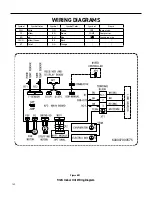
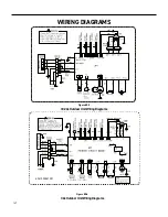
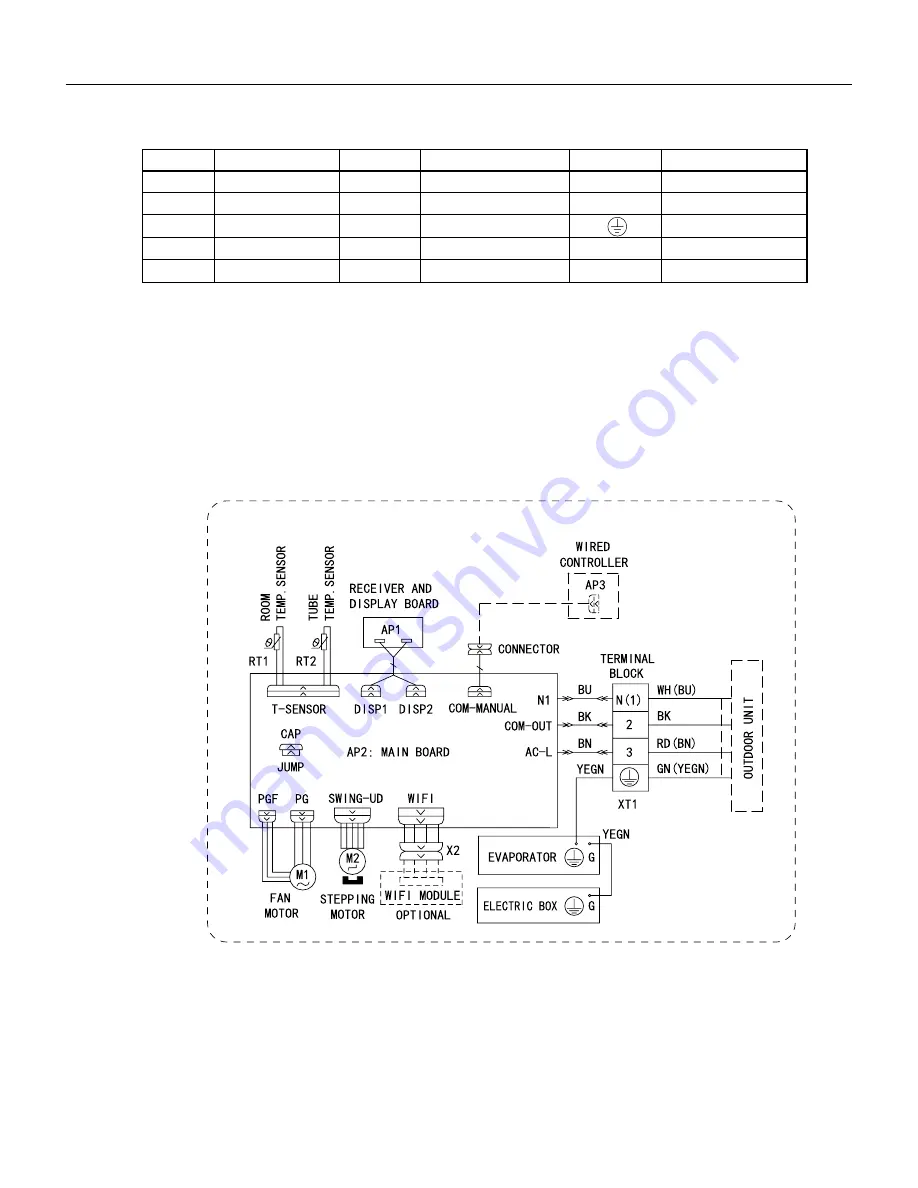
Figure 802
18-24k Indoor Unit Wiring Diagram
WIRING DIAGRAMS
●
Indoor Unit
Symbol
Symbol Color
Symbol
Symbol Color
Symbol
Name
WH
White
GN
Green
CAP
Jumper cap
YE
Yellow
BN
Brown
COMP
Compressor
RD
Red
BU
Blue
Grounding wire
YEGN
Yellow/Green
BK
Black
/
/
VT
Violet
OG
Orange
/
/
Note: Jumper cap is used to determine fan speed and the swing angle of horizontal lover for this model.
600007000575
Содержание FSHW091
Страница 8: ...8 INTRODUCTION FSHSW09A1A FSHSW12A1A Figure 102 Indoor Units FSHSW18A3A FSHSW24A3A FSHSW36A3A ...
Страница 47: ...47 INSTALLATION ...
Страница 48: ...48 INSTALLATION Installation Tools ...
Страница 72: ...72 WIRED CONTROLLER Display ...
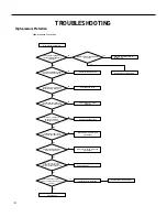
Страница 122: ...122 TROUBLESHOOTING Malfunction of IDUFanMotorU8 Service Manual No Start End ...
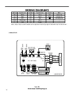
Страница 146: ...146 WIRING DIAGRAMS Figure 8054 9 12KOutdoorUnitWiringDiagrams 60000706067401 3 2 N 1 C3 C4 ...
Страница 147: ...147 WIRING DIAGRAMS Figure 805 18 24kOutdoorUnitWiringDiagrams Figure 806 36kOutdoorUnitWiringDiagrams 6361000047001 ...
Страница 158: ...158 FIgure 906 PARTS CATALOG 9KOutdoorUnit 28 27 29 31 30 32 ...
Страница 160: ...160 PARTS CATALOG 12k OutdoorUnit 28 27 29 31 30 32 FIgure 907 ...

