64
PB
REMOVAL
Indoor Unit
a
b
Note:
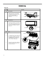
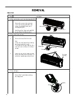
Screw off the 2 screws that are locking
the display board.
1.Open the screw caps before removing
the screws around the air outlet.
2.The quantity of screws fixing the front
case sub-assy is different for different
models.
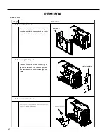
5. Remove front case sub-assy
6. Remove display
Bottom case
Front case
sub-assy
Display
Screws
Clasp
Screw caps
Loosen the connection clasps between
front case sub-assy and bottom case. Lift
up the front case sub-assy and take it out.
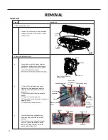
Screws
Screw
Detecting plate(WIFI)
2
Procedure
Step
4. Remove electric box cover 2 and detecting plate(WIFI)
Remove the screws on the electric box
cover 2 and detecting plate(WIFI), then
remove the electric box cover 2 and
detecting plate(WIFI).
Note:the position of detection board(WIFI)
may be different for different models.
Содержание FSHW091
Страница 8: ...8 INTRODUCTION FSHSW09A1A FSHSW12A1A Figure 102 Indoor Units FSHSW18A3A FSHSW24A3A FSHSW36A3A ...
Страница 47: ...47 INSTALLATION ...
Страница 48: ...48 INSTALLATION Installation Tools ...
Страница 72: ...72 WIRED CONTROLLER Display ...
Страница 122: ...122 TROUBLESHOOTING Malfunction of IDUFanMotorU8 Service Manual No Start End ...
Страница 146: ...146 WIRING DIAGRAMS Figure 8054 9 12KOutdoorUnitWiringDiagrams 60000706067401 3 2 N 1 C3 C4 ...
Страница 147: ...147 WIRING DIAGRAMS Figure 805 18 24kOutdoorUnitWiringDiagrams Figure 806 36kOutdoorUnitWiringDiagrams 6361000047001 ...
Страница 158: ...158 FIgure 906 PARTS CATALOG 9KOutdoorUnit 28 27 29 31 30 32 ...
Страница 160: ...160 PARTS CATALOG 12k OutdoorUnit 28 27 29 31 30 32 FIgure 907 ...

