Frick XLP3 Скачать руководство пользователя страница 26

140.925-IOM (APR 2019)

Page 26

XLP3 EVAPORATIVE CONDENSERS

MAINTENANCE

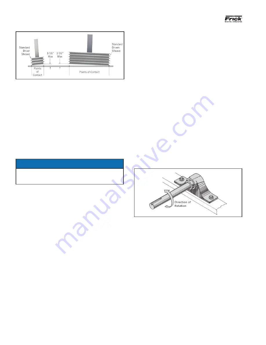
Figure 24. Drive Alignment

Adjustable Motor Base

Coat the motor base slides and adjusting screws (refer to Figure 
23) prior to start-up, every three months while in operation, 
and following shutdown. Use good quality, corrosion inhibiting 
grease such as one of those recommended for lubricating the 
fan shaft bearings below.

Fan Motor Inspection & Maintenance

•  Clean the outside of the motor at least quarterly to ensure 

proper motor cooling.

•  After prolonged shutdowns, check the motor insulation 

with an insulation tester prior to restarting the motor.

•  Check the motor voltage and current following start-up 

and every three months while in operation.

NOTICE

Check to ensure the controls for the fan motor are set to 

allow a maximum of six on-off cycles per hour to prevent 

motor overload.

Fan Shaft Bearing Inspection & Maintenance

•  For all units ordered with the Belt Drive Fan System, two 

pillow block ball bearings support the fan shaft and are 
provided with extended lube lines as standard on the XLP3 
Evaporative Condenser. Each bearing is equipped with a 
lubrication fitting and a locking collar to keep out moisture.

•  Only lubricate the bearings with a manual grease gun or 

Frick’s optional Automatic Bearing Greaser. Do not use 
high-pressure grease guns since they may rupture the 
bearing seals or the extended lubrication lines.

•  Only lubricate the bearings with one of the following 

compatible water resistant greases which are suitable for 
ambient temperatures ranging from -65°F (-53.9°C) to 
+250°F (121.1°C).

  •  Amoco - Rycon Premium #3
  •  Chevron - SRI
  •  Citgo - Polyurea MP2™
  •  Conoco - Polyurea 2™
  •  Exxon - Polyrex® EM
  •  Exxon - Unirex N™
  •  MobilGrease® - AW2
  •  Shell - Gadus S2 V100 3
  •  Shell - Gadus S3 T100 2
  •  SKF - LGHP2™
  •  Unocal 76 - Unilife Grease™

•  Lubricate the bearings as follows:
 • 

Initial Start-Up:

 Normally, no lubrication is required 

since the bearings have been lubricated at the factory 
prior to shipment. However, if the unit has been stored 
at the job site for more than three months, both 
bearings should be lubricated with new grease before 
initial operation. When lubricating, purge the old grease 
from the bearing by gradually adding grease until a bead 
of new grease appears at the seal on the underside of 
the bearing.

 • 

Seasonal Start-Up:

 Purge the bearings with new 

grease prior to start-up.

 • 

Operation:

 Purge the bearings with new grease every 

three months while in operation.

 • 

Extended Shutdown:

 Purge the bearings with new 

grease prior to any prolonged storage or downtime.

Locking Collars

Each eccentric locking collar should be checked quarterly to 
ensure that the inner bearing race is secured to the fan shaft. 
The locking collar can be set using the following procedure (see 
Figure 25):

•  Loosen the set screw.
•  Using a drift pin or center punch, tap the collar (in the hole 

provided) tangentially in the direction of rotation while 
holding the shaft.

•  Retighten the set screw.

Figure 25 — Locking Collar Assembly

Water Distribution System and Heat Transfer Section

Water is distributed through a corrosion resistant polyvinyl chlo-
ride (PVC) spray distribution system. The drift eliminators are 
made of PVC, which requires no protection against rot, decay, 
rust, or biological attack.

The inspection procedure is as follows:

•  Shut off the fan and lock out and tag out the fan and pump 

motors.

•  Remove drift eliminators to allow a clear view of the spray 

distribution system and nozzle patterns.

•  Start the recirculating pump. Make sure the fan motor is 

locked out and tagged out. Check to see if the nozzles are 
all spraying consistently and producing the spray pattern 
shown in Figure 26.

•  Clean any nozzles that are clogged. If necessary, the 

nozzle and rubber grommet may be removed for cleaning. 
If additional cleaning is necessary the branch may be 

Содержание XLP3

Страница 1: ...ive Condenser THIS MANUAL CONTAINS RIGGING ASSEMBLY START UP AND MAINTENANCE INSTRUCTIONS READ THOROUGHLY BEFORE BEGINNING INSTALLATION FAILURE TO FOLLOW THESE INSTRUCTIONS MAY RESULT IN PERSONAL INJU...

Страница 2: ...TIONS 14 START UP PROCEDURE 15 Considerations for Initial Start Up 15 General 15 Cleaning 15 Inspection 15 Start up 15 EXTENDED SHUTDOWN 16 PROLONGED OUTDOOR STORAGE 16 Storage Preparation 16 Motor Re...

Страница 3: ...afety Cage Optional Coil Connection Refrigerant Vapor In Coil Connection Refrig erant Liquid Out Terminal Box Pump Factory Pre Assembled Platforms with Perimeter Handrails Optional BranchLokTM Removal...

Страница 4: ...ellaneous parts are included with the shipment and where they are packed This envelope will be attached to the side of the unit or located in a box inside the unit INSTALLATION Unit Weights Before rig...

Страница 5: ...to ensure an airtight seal between the top and bottom section Install flat butyl sealer tape Frick part 554000 supplied with the unit on the mating flanges of the lower section in a continuous line A...

Страница 6: ...basin section sealer tape must be applied to both cross flanges see Figure 3 10 On units operating with a remote sump tank install a bleed line with valve between the system circulating pump discharg...

Страница 7: ...lease ensure that the correct voltage is supplied to the unit If unsure check your unit s submittal to verify that the provided power matches your unit On the factory terminal box remove the NEMA plug...

Страница 8: ...nd Figure 9 Detail A Check your submittal for the ladder orientation ordered Attach the ladder to the platform and fasten the lower and intermediate brackets to the ladder side rails as shown in Figur...

Страница 9: ...DENSERS INSTALLATION Figure 9 End Ladder Installation Detail A End Ladder Bracket Detail A Perimeter Guardrail Installation Detail B Corner Guardrail Installation Detail C Perimeter Guardrail Installa...

Страница 10: ...are provided for all handrail openings and all components are designed to meet OSHA requirements Share two lower fasteners on upper ladder bracket Upper ladder bracket Hoop Detail D Figure 11 Safety...

Страница 11: ...per the control panel wiring diagram 5 Connect the heater power wire conduit s to the heater power wire hub s provided on the control panel Make sure the con nection is watertight and secure Pull the...

Страница 12: ...Control Panel L1 L2 L3 Controller Liquid Level Temperature Combination Series TL Solitech CT N C NO NC T1 T2 G1 G2 Shielded Cable Assembly Sensor Probe Cord G2 G1 T2 T1 SH No 1 Heater 40 24 16 12 8 1...

Страница 13: ...ter basin a For connections 3 or less score the TripleGuard Corrosion Protection System with a hole saw as shown in Figure 14 b For connections 3 or greater proceed to step 4 4 Cut the hole from the o...

Страница 14: ...fan screens access panels and access doors in place CAUTION All electrical mechanical and rotating machinery are potential hazards particularly for those not familiar with their design construction an...

Страница 15: ...locked out and tagged out Inspection Conduct external inspection of the equipment Check for leaks corrosion and any structural damage Conduct internal inspection of the equipment Check for anything u...

Страница 16: ...fer to the manufacturer s guidelines before loading unloading weight from the unit Disconnect lock out and tag out the fans pump and motors Close the shut off valve in the make up water line supplied...

Страница 17: ...ump motors are disconnected locked out and tagged out Belt Drive Fan System Frick standard motors are designed for storage at ambient temperatures of 20 F to 104 F 28 9 C to 40 C Prolonged periods of...

Страница 18: ...system performance or create a safety hazard Fan Section Icing Protection There are three basic operational methods which can be used to provide the system s required cooling temperature setting fan...

Страница 19: ...heaters are sized for the specific unit The heating element has an enclosure that is suitable for outdoor use Annually inspect the basin heater prior to the risk of reaching freezing operating condit...

Страница 20: ...bration cutout switch is not needed Mechanical Vibration Cutout Switch Standard Set Point Adjustment When Installed 1 For safety turn off then lock and tag out the electrical supply to the fan motor s...

Страница 21: ...Control Panel L1 L2 L3 Controller Liquid Level Temperature Combination Series TL Solitech CT N C NO NC T1 T2 G1 G2 Shielded Cable Assembly Sensor Probe Cord G2 G1 T2 T1 SH No 1 Heater 40 24 16 12 8 10...

Страница 22: ...ent Staging Down Turn off the fan motor No need for delays NOTICE For a unit with a VFD with a switching frequency of 2 5 kHz the line lead length cannot exceed 100 feet If the switching frequency is...

Страница 23: ...the VFD on and verify that the fan is turning in the correct direction Using the VFD slowly about 1 RPM increase every five to ten seconds adjust the motor speed from the lowest limit to full speed wh...

Страница 24: ...tors are disconnected locked out and tagged out Blade Pitch Check to ensure that the blades are all at the same pitch If uncertain measure the pitch with an inclinometer All blades should be within 1...

Страница 25: ...s necessary Readjust tension at least once every three months Belt tension check Place a straight edge along the belt from sheave to sheave as shown in Figure 22a or use a tape measure as shown in Fig...

Страница 26: ...the bearings as follows Initial Start Up Normally no lubrication is required since the bearings have been lubricated at the factory prior to shipment However if the unit has been stored at the job si...

Страница 27: ...the valve seat if necessary Maintain the make up water supply pressure between 15 psig and 50 psig for proper operation Frick recommends a pressure regulator valve provided by others for pressures ove...

Страница 28: ...tection System for signs of deep scratches or blemishes especially in areas with field penetrations Touch these up with 3M Windo Weld Super Fast Urethane which is available through your local Frick Re...

Страница 29: ...Dissolved Solids TDS 1 500 ppm 2 050 ppm 2 050 ppm 2 500 ppm Conductivity 2 400 micromhos cm 3 300 micromhos cm 3 300 micromhos cm 4 000 micromhos cm Alkalinity as CaCO3 500 ppm 2 600 ppm 2 600 ppm 2...

Страница 30: ...methyl or ethyl alcohol or mineral spirits Stainless steel wipes or glass cleaners commonly available in stores may also be used NOTICE Never use chloride or chlorine based solvents such as bleach or...

Страница 31: ...reatment expert Bleed Line Calculations Bleed rate is determined by the fol lowing formula B E n 1 Where B Bleed Rate USGPM E Evaporation Rate USGPM Q USGPM x R F x 0 001 Q Process Fluid Flow Rate USG...

Страница 32: ...for proper rotation X Check general condition of the fan X X Check fan for uniform pitch 4 X Check fan for rotation without obstruction X X Check and recoat steel shafts with RUST VETO 4 X X X Check...

Страница 33: ...140 925 IOM APR 2019 Page 33 XLP3 EVAPORATIVE CONDENSERS MAINTENANCE NOTES...

Страница 34: ...ynesboro PA 17268 1206 USA Phone 717 762 2121 FAX 717 762 8624 www johnsoncontrols com frick Form 140 925 IOM 2019 04 Supersedes Nothing Subject to change without notice Published in USA 04 19 PDF 201...

Отзывы: