background image

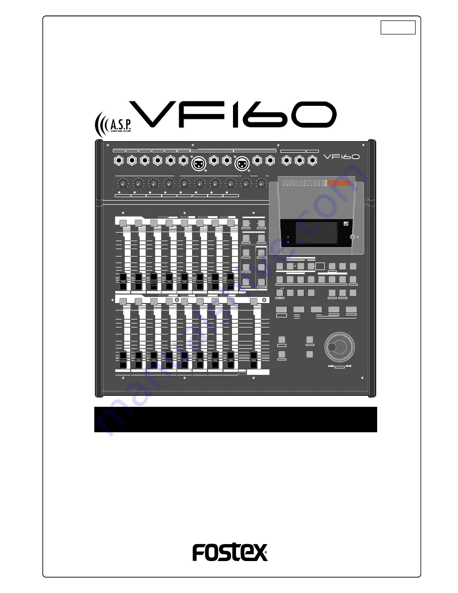
Digital Multitracker

Operation Manual

8588 008 100

(356891)

ACCESS

PHANTOM

INPUT SEL

SOURCE

REC ASSIGN

BUSS

DIRECT

REC TRK

REC TRK

AUTO RTN

AUTO PUNCH

START

IN

OUT

END

IN

ALIGN SEL

OUT

DISP SEL

PGM SEL

SETUP

INT

MIXDOWN

A RTN

A PLAY

SCENE SEQ.

TIME BASE

CLIPBOARD

MARK

1

2

3

4

5

6

7

HOLD/

STORE

EDIT

UNDO

/REDO

VARI

PITCH

LOCATE

SCRUB

P.EDIT

EVT MEM

F FWD

REWIND

PLAY

STOP

RECORD

CLIPBOARD PLAY

LOCATE ABS 0

LOCATE REC END

PREV

NEXT

JOG

SHUTTLE

AUTO

PUNCH

EXIT/NO

EJECT

ENTER/YES

FADER

ADJUST

LEVEL

ADJUST

SHIFT

CH PARAM EDIT

CH VIEW

FADER

TRACK

LO-G

PAN

PRE/POST

MID-G/F/Q

AUX1/AUX2

COMP

PRE/POST

EFF1/EFF2

HI-G/F/Q

EQ/COMP

MUTE

MUTE

EFF1

EFF2

EFF EDIT

MAP

DIRECT RCL

CLEAR

STORE

RECALL

SCENE

MUTE

OFF

PLAY

GREEN

REC

RED

INPUT

ORANGE

CH STATUS

CH STATUS/CH SEL

1/9/A

2/10/B

3/11/C

4/12/D

5/13/E

6/14/F

7/15/G

8/16/H

PEAK

PEAK

PEAK

PEAK

PEAK

PEAK

PEAK

PEAK

LINE

MIC

LINE

MIC

LINE

MIC

LINE

MIC

LINE

MIC

LINE

MIC

LINE

MIC

LINE

MIC

0

10

0

10

PHONES

MON OUT

TRIM

INPUT

6/14/F

7/15/G

5/13/E

4/12/D

3/11/C

2/10/B

1/9/A

INSERT

UNBAL

BAL

8/16/H

BAL

INSERT

UNBAL

R

L

PHONES

MON OUT

MUTE

OFF

PLAY

GREEN

REC

RED

INPUT

ORANGE

CH STATUS

CH STATUS/CH SEL

1

2

3

4

5

6

7

8

9

A

10

B

11

C

12

D

13

E

14

F

15

G

16

H

MASTER

TRACK

INPUT

-60

-50

-40

-30

-20

-10

0

+6

-60

-50

-40

-30

-20

-10

0

+6

-60

-50

-40

-30

-20

-10

0

+6

-60

-50

-40

-30

-20

-10

0

+6

-60

-50

-40

-30

-20

-10

0

+6

-

-

-

-

-

ACCESS

PHANTOM

OPTICAL

Содержание VF-160

Страница 1: ...UX1 AUX2 COMP PRE POST EFF1 EFF2 HI G F Q EQ COMP MUTE MUTE EFF1 EFF2 EFF EDIT MAP DIRECT RCL CLEAR STORE RECALL SCENE MUTE OFF PLAY GREEN REC RED INPUT ORANGE CH STATUS CH STATUS CH SEL 1 9 A 2 10 B 3 11 C 4 12 D 5 13 E 6 14 F 7 15 G 8 16 H PEAK PEAK PEAK PEAK PEAK PEAK PEAK PEAK LINE MIC LINE MIC LINE MIC LINE MIC LINE MIC LINE MIC LINE MIC LINE MIC 0 10 0 10 PHONES MON OUT TRIM INPUT 6 14 F 7 1...

Страница 2: ...l triangle is intended to alert the user to the presence of uninsulated dangerous voltage within the product s enclosure that may be of sufficient magnitude to constitute a risk of electric shock to persons The exclamation point within an equilateral triangle is intended to alert the user to the presence of important operating and maintenance servicing instructions in the literature accompanying t...

Страница 3: ...160 while the hard disk is accessing data the HD ACCESS LED is lit or flashing Otherwise not only will you lose recorded data but you may damage to the VF160 Fostex is not responsible for the data lost during operation of the VF160 Before you change the location of the VF160 pack theunitintheshippingcartonoranimpact resistant case Make sure that the VF160 is kept free from external vibration or im...

Страница 4: ...o use the condenser type microphone Please read page 140 I want to use the equalizer at recording Please read pages 40 and 51 I want to use the internal effector at recording Please read pages 41 50 and 56 I want to listen any number of times to playback of a recorded tune Please read page 69 I want to locate to the desired point Please read page 34 I want to exchange tracks Please read pages 39 a...

Страница 5: ...and 50 I want to delete an unnecessary program Please read page 71 I want to locate to a point previous to the desired point Please read page 130 I want to operate the faders in pairs Please read page 139 I want to make a tempo map Please read pages 126 and 128 I want to mixdown without using external equipment Please read page 79 I want to format the backup disks Please read page 102 I want to se...

Страница 6: ...hapter 2 Basic Recording and Playback Initial condition when the power is turned on 49 Operations while the Normal Display is shown 49 Fader 49 ChannelmuteandSolofunction 49 Masterchannelmute 49 AdatMixerMode On Off 49 ChannelParameterEdit 50 AdjustingPAN 50 AdjustingEQ 51 ControllingEffectSendLevel 52 SelectingPre PostofEffectSends 52 ControllingAUXSendLevel 53 SelectingPre PostofAUXSends 53 Cont...

Страница 7: ...ilence atthebeginningofasong 83 ApplicationsofBUSSRECORD 85 RecordbyMixingtheInputSoundandPlaysound 85 Ping PongRECORD 86 MetronomeFunction 87 DigitalRecording 88 DigitalRecordingfromanExternalDigitalDevice 88 Recording16TracksattheSameTime 89 MIDIClockSyncSystem 90 MIDISync MIDIMachineControlSystem 91 External MIDI equipment Sync System by the Slave Mode 93 Applications example of Adat Mixer Mode...

Страница 8: ...clock withbar beatresolution Six editing memory points and 7 marked points 0 10 second pre roll time settings Introduction Congratulations You have chosen a truly unique multitracking device TheVF160FostexDigitalMultitrackerfeaturesamyriad of high tech functions These include a digital mixer incorporateshigh performanceDSPmulti effectmade possible using the Fostex original A S P Fostex Advanced Si...

Страница 9: ...e This recording mode is mainly used to Record sounds while applying equalizer and built in effects and Record ping pong recording etc signals mixed on multiple channels on two or one track ThismodeisusedtorecordsignalssenttotheRECBUSS thatistherecordingbuss aftertheinputsignalortrack play sound is processed through the mixer and level tuned or equalized Built in effect signals can also be sent to...

Страница 10: ...INPUT SEL key DIRECT REC TRK key BUSS REC TRK key BUSS SOURCE key Tips Pressingthe CHSTATUS CHSEL keyofchannel1 8 or channel 9 16 while holding down the SHIFT key switchesarmsalltracks1through8 or9through16 simultaneously For BUSS recording INPUT SEL BUSS SOURCE and BUSS REC TRK keys are used The following figure shows that track 1 is armed READY sothatinputAsignalcanberecordedontrack 1 INPUT SEL ...

Страница 11: ...basis Thevalueindicatestheavailablerecordable time and disk space when recording one mono track ABS0 00m 00s 05m 00s 10m 00s REC END 15m 00s 23h 59m 59s recorded area recorded area unrecorded area unrecorded area You can record at any point within 24 hours in ABS time 5 minute recording unrecorded 5 minute recording 24 hour recording recorded area recorded area unrecorded area remain Program P01 T...

Страница 12: ...k sound Playback monitor Playback sound Playback monitor Input signal Input monitor Input signal Input monitor Playback sound Playback monitor Playback sound Playback monitor Playback sound Playback monitor Playback sound Playback monitor Playback sound Playback monitor Playback sound Playback monitor Playback sound Playback monitor Playback sound Playback monitor A mono track refers to one track ...

Страница 13: ... possible to eliminate this distortion from the sound with the mixer or recorder Therefore it is important to tune the TRIM to a level where the PEAK LED fluctuates between the illuminating or not point at the maximum volume of the signal input Clip level Clip level Appropriate gain Excessive gain A Silence B Silence Rec B C Rec B Rec C Silence D Rec B Rec C Silence Silence Rec D E Rec E Silence S...

Страница 14: ...as the offset position The location of the bar thereafter is determined according to the beat and tempo setting The default setting of ABS 0 is set at Bar 002 however this setting is variable between Bars 009 and 002 MTCsettheABS0locationtoMTC H M S Inotherwords MTCsetsthetimebasetostartMTCfromacertaintime which servesastheoffsettime tosynchronizethefollowing24hour MTC time base with the ABS to co...

Страница 15: ...MID G F Q AUX1 AUX2 COMP PRE POST EFF1 EFF2 HI G F Q EQ COMP MUTE MUTE EFF1 EFF2 EFF EDIT MAP DIRECT RCL CLEAR STORE RECALL SCENE MUTE OFF PLAY GREEN REC RED INPUT ORANGE CH STATUS CH STATUS CH SEL 1 9 A 2 10 B 3 11 C 4 12 D 5 13 E 6 14 F 7 15 G 8 16 H PEAK PEAK PEAK PEAK PEAK PEAK PEAK PEAK LINE MIC LINE MIC LINE MIC LINE MIC LINE MIC LINE MIC LINE MIC LINE MIC 0 10 0 10 PHONES MON OUT TRIM INPUT...

Страница 16: ...onnect an external effector since the ø6 TRS phones jack is used 5 MON OUT Monitor Output Jack L R Connect a speaker with internal amp or amp speaker for monitoring purposes Standard Output Level 10dBV Connector Phones jack 6 PHONES Headphones Jack Headphones connection for monitoring purposes Connector TRS Phones jack 7 PEAK LED 1 to 8 Lights ON if the input signal is approx 2dB lower than the cl...

Страница 17: ...ring the recording process 12 Channel Fader channels 1 16 The1 8channelfadersareusedtoadjusttheaudiolevel TRACK of tracks 1 8 The 9 16 channel faders are used to adjust the sound levelofsignalsinputintoAtoHoraudiolevels TRACK of 9 16 Use the INPUT SEL key to choose which level to adjust 13 SCENE RECALL DIRECT RCL Key This is used to recall the scene memory Press this key while the SHIFT key is dep...

Страница 18: ...ssed to CHECK CHANGEthePRE POSTsettingsofAUX1orAUX 2 Use the CH STATUS CH SEL Key to select the channel to change any settings together 20 CH PARAM EDIT EQ COMP MID G F Q Key This is used to CHECK CHANGE the midrange frequencies of the parametric equalizer settings Press this key while the SHIFT key is depressed to CHECK CHANGE the settings 21 CH PARAM EDIT PAN FADER Key This is used to CHECK CHAN...

Страница 19: ...ording to the connection jack a Current location of TIME BASE selected Shows the current location of the sound b REMAINING TIME BASE Selected time remaining Shows the time remaining and space available on the disk for recordings in terms of mono track c MTC Time Input Shows the MTC time input in the MIDI IN jack This is a convenience for operations as a slave device Theusercanswitchbetweentimebase...

Страница 20: ...ttheendpoint CLIPBOARDOUTPOINT whencopying from or pasting to the clipboard Press this key while the SHIFT key is depressed to CHECK CHANGE the parameters saved in MARK7 This can be used as Locate Memory 39 A RTN A PLAY SCENE SEQ Key Every time this key is pressed the mode switches from AutoPlay AutoReturn AutoRepeat OFF andthis mode is shown on the LCD Pressthiskeywhilethe SHIFT keyisdepressedtot...

Страница 21: ... dial is turned The jog dial can be used to increase decrease the parameter settings during the editing process For more details refer to the respective instructions of each item 46 SCRUB Key This is used to digitally scrub sounds in the FWD and REV direction without any change in pitch 47 RECORD AUTO PUNCH Key Pressthe PLAY keywhilethiskeyisdepressed orpress this key while the PLAY key is depress...

Страница 22: ...2 signals Standard Output Level 10dBV Use a Y cable as shown below to connect an external effector since the ø6 TRS Phones jack is used MIDI control signals such as MMC MIDI Machine Control is mainly input Connector DIN 5 PIN 64 MIDI OUT Jack Connect to the MIDI IN jack of an external MIDI device MIDI synchronization signals such as MTC MIDI Time Code and MIDI clock signals song position pointers ...

Страница 23: ...ial to highlight the Disk Format menu title IDE indicatesthecurrentdrive SCSI indicatesthebackup SCSI drive 4 Press the ENTER YES key while IDE is highlighted The menu to select the format type appears Thedisplaywillappearasfollows accordingtotheprevious format type represents the name of the drive The hard disk formatted in the Standard type upon newly formatting the hard disk will show Standard ...

Страница 24: ... process or any hard disk damages if the customer decides to replace their own hard disk on their own Operation Confirmed HD Backup Media List for the VF160 The updated information on the operation confirmed HD and backup media for VF160 is mentioned in the following Fostex international web site http www fostex co jp int index htm For those who are unable to check our web site please contact the ...

Страница 25: ...earlier carefully house the hard disk at the bottom of the main unit and cover it with the cushion 6 After checking that the cables etc are not sticking out from the main unit put the panel onto the hard disk and the case Align the position of screw holes on the panel case with theVF160bottompanelscrewholesandfixthepanel case using the four screws to the VF160 main unit When the new hard disk is s...

Страница 26: ...at will appear on the LCD The menu will automatically go to the SETUP mode The display showing the Disk Format menu appears 2 Press the ENTER YES key The drive selection display appears IDE will be flashed 3 Pressthe ENTER YES keywherethe IDE isflashed The menu to select the format type appears represents the name of the drive CAUTION Either the Standard or Quick format type can be selected Howeve...

Страница 27: ... any time by playing back program 1 see page 31 for details about how to play back a program Note that you cannot record a new material on program 1 if a demonstration song is recorded on program 1 Therefore before starting recording for the first time you must carry out any of the following operations Note You can start recording without the need for carrying out any of the following operations i...

Страница 28: ... FOOT SW DIGITAL DATA MIDI ST OUT AUX SEND CAUTION RISK OF ELECTRIC SHOCK DO NOT OPEN RISQUE DE CHOC ELECTRIQUE NE PAS OUVRIR WARNING TO REDUCE THE RISK OF FIRE OR ELECTRIC SHOCK DO NOT EXPOSE THIS EQUIPMENT TO RAIN OR MOISTURE Monitor Amplifier Monitor Speaker Headphones Microphone Guitar Processor Keyboard Microphone Unbalanced output Balanced output Input Output Compressor Limitter Foot Switch ...

Страница 29: ...the power ON is called the Normal Display The NormalDisplay showsthefollowingitemsforthe 3 time bases Current Location Program Number Program Title Scene Number Scene Name Level Meter of Tracks 1 16 Stereo OUT L R Master Level Meter Normal display Switching the Time Base The user can switch between time bases by pressing the DISP SEL key while the SHIFT key is depressed In this case the time base ...

Страница 30: ...16 characters of the program title are shown Scene number and scene name The first 16 characters of the scene name are shown Level meter of tracks 1 to 16 L R master level meter 1 The REMAINING time display appears as follows according to the time base that has been selected Time Base ABS and MTC Time Base BAR BEAT CLK 2 Icons of the program setup details appear at the right side of the menu Refer...

Страница 31: ... 5 13 6 14 7 15 8 16 1 2 3 4 5 6 7 8 9 10 11 12 13 14 15 16 RECORDER 1 16 Track INPUT 6 14 F 7 15 G 5 13 E 4 12 D 3 11 C 2 10 B 1 9 A INSERT UNBAL BAL 8 16 H BAL INSERT UNBAL 1 9 A 2 10 B 3 11 C 4 12 D 5 13 E 6 14 F 7 15 G 8 16 H PEAK PEAK PEAK PEAK PEAK PEAK PEAK PEAK LINE MIC LINE MIC LINE MIC LINE MIC LINE MIC LINE MIC LINE MIC LINE MIC TRIM ACCESS PHANTOM INPUT SEL SOURCE REC ASSIGN BUSS DIREC...

Страница 32: ...1 9 A gain to an optimal level The guideline for optimal gain is the border of the PEAK LED lighting ON or OFF when the sound source is at the maximum volume Adjustments should also ensure that the signal does not exceed 0 on the LCD level meter To listen to the sound turn up the MON OUT knob or PHONES knob WARNING Be careful not to excessively raise the volume of the MON OUT or PHONES level Prolo...

Страница 33: ...MON OUT TRIM INPUT 6 14 F 7 15 G 5 13 E 4 12 D 3 11 C 2 10 B 1 9 A INSERT UNBAL BAL 8 16 H BAL INSERT UNBAL R L PHONES MON OUT MUTE OFF PLAY GREEN REC RED INPUT ORANGE CH STATUS CH STATUS CH SEL 1 2 3 4 5 6 7 8 9 A 10 B 11 C 12 D 13 E 14 F 15 G 16 H MASTER TRACK INPUT 60 50 40 30 20 10 0 6 60 50 40 30 20 10 0 6 60 50 40 30 20 10 0 6 60 50 40 30 20 10 0 6 60 50 40 30 20 10 0 6 ACCESS PHANTOM OPTICA...

Страница 34: ...c Mode Change appears and Sure flashes on the screen Pressing the ENTER YES key cancels the selection of tracksfortheDIRECTrecordingandchangesthedis playtothetrackselectionscreenfortheBUSSrecord ing Tips UNDO REDO Press the UNDO REDO key after recording to return to the prerecording state UNDO Press the UNDO REDO key again to return to the original state of the recording on two tracks REDO Locate ...

Страница 35: ...lashing column cursor H M S F SF or BAR BEAT CLK using the JOG dial Move the flashing column cursor by pressing the HOLD key 3 Press the STORE key RED Light ON 3 1 Press a voluntary Memory key ThetimemodifiedissavedasthetimepointoftheMemory Key and the system returns to the Normal Display 3 2 Pressthe MARK1 7 keywhilethe SHIFT keyisdepressed The time modified is saved as a Mark Memory of MARK 1 7 ...

Страница 36: ...can delete unnecessary event memories See Edit ing the event map in Advanced mixer operations de scribed later for details 3 After viewing the screen press the EXIT NO key The display returns to the Normal display 07M30S 05M00S 02M30S ABS0 17M30S 15M00S 12M30S 12M30S 2 3 6 7 1 5 4 2 Press the STORE key Thekeylightsup inred and HitAnyMemoryKeys appears on the screen 3 Press the LOCATE EVT MEM key w...

Страница 37: ...rsing the recording Rhrsl On will appear on the LCD then RHSL will light ON Rehearsal instructions are the same as recording with the foot switch However stepping on the foot switch will go to input monitor andsteppingonitagainwillcancelit Tocancel the rehearsal mode step on the foot switch again while the STOP keyisdepressed RhrslOff willappearonthe LCD then RHSL will light OFF 1 Pressthe PLAY ke...

Страница 38: ...ugh recording is not actually executed the monitor signal for a record armed track changes to input at the punch in point and returns to source at the punch out point You can check or adjust the record level and timing in the rehearsal mode as many times as you want until you are satisfied 4 Press the STOP key to stop the VF160 1 While the system is in the PLAY or STOP mode press the HOLD key at t...

Страница 39: ... Dependingontheselectedunit thetrackindicationonthe right changes see the figure below Tips SelectErr appearsontheLCDandtheexchangeprocess is invalidated if the same track is selected for the track toexchangefromandtracktoexchangeand ENTER YES is pressed Ex 03 03 and so on Track Exchange Tips TheTrackExchangecanbedoneamongall24real and additional tracks as shown in the figure be low You can exchan...

Страница 40: ...S CHSEL key of that channel then go to Step 3 5 Press the EXIT NO key when adjustments are completed The system returns to the Normal Display Tips For fader paired channels set by the Pair fader setting menu in the Setup mode controlling EQ settings for one channel affects both channels simultaneously See page 138 for details about how to pair faders 1 1 Press the HI G F Q key The menu to set the ...

Страница 41: ... pess the EXIT NO key The system returns to the Normal Display 4 Toadjustotherchannels pressthe CHSTATUS CHSEL key of that channel 5 When adjustments are completed press the EXIT NO key The system returns to the Normal Display Tips For fader paired channels set by the Pair fader setting menuintheSetupmode controllingthelevelforonechan nel affects both channels simultaneously See page 138 for detai...

Страница 42: ...errecorder has a S P DIF optical digital input Usethe FostexCOP 1 96k forconnectionsifthe master recorder has a S P DIF coaxial digital input jack 3 Fine tune the output level of the VF160 master fader In General the optimal level is when the level meter of the master recorder is 0 at the maximum volume of VF160 Note that any level exceeding 0 may cause sound distortion 4 Startrecordingwiththemast...

Страница 43: ...tputsoundofthetrackscorrespondingtoch9to16 soitisnotpossibletogototheREADYstateusing the BUSS REC TRK key WARNING Precautions for when selecting a source channel with the BUSS SOURCE key when key is flashing in GREEN A channel in which the CH STATUS CH SEL key light is OFF is selectable The channel selected will either have a flashing ORANGE or GREEN CH STATUS CH SEL key The CH STATUS CH SEL key t...

Страница 44: ... MEM F FWD REWIND PLAY STOP RECORD CLIPBOARD PLAY LOCATE ABS 0 LOCATE REC END PREV NEXT JOG SHUTTLE AUTO PUNCH EXIT NO EJECT ENTER YES FADER ADJUST LEVEL ADJUST SHIFT CH PARAM EDIT CH VIEW FADER TRACK LO G PAN PRE POST MID G F Q AUX1 AUX2 COMP PRE POST EFF1 EFF2 HI G F Q EQ COMP MUTE MUTE EFF1 EFF2 EFF EDIT MAP DIRECT RCL CLEAR STORE RECALL SCENE MUTE OFF PLAY GREEN REC RED INPUT ORANGE CH STATUS ...

Страница 45: ...othisdisplayfromtheNormalDisplay ThedefaultsettingoftheRECBUSSMasterLevelisfac tory preset to level 80 Use the JOG dial to turn the RECLVL knob on the LCD as shown below and adjust the number setting in real time The REC BUSS Master Level can also be adjusted adjustable range 00 99 REC BUSS Master Level adjustment icon REC BUSS Master Level appears Tips Changing the recording mode To change the BU...

Страница 46: ...BUSS DIRECT REC TRK REC TRK AUTO RTN AUTO PUNCH START IN OUT END IN ALIGN SEL OUT DISP SEL PGM SEL SETUP INT MIXDOWN A RTN A PLAY SCENE SEQ TIME BASE CLIPBOARD MARK 1 2 3 4 5 6 7 HOLD STORE EDIT UNDO REDO VARI PITCH LOCATE SCRUB P EDIT EVT MEM F FWD REWIND PLAY STOP RECORD CLIPBOARD PLAY LOCATE ABS 0 LOCATE REC END PREV NEXT JOG SHUTTLE AUTO PUNCH EXIT NO EJECT ENTER YES FADER ADJUST LEVEL ADJUST ...

Страница 47: ...starttime 2 Press the PLAY key to play the VF160 Adjusttheplayleveloftracks7and8withthech7 8faders to check listen to the sound recorded Preparing to Record Note If input signals are started for ch9 16 faders the play sounds of the corresponding track can no longer be heard and you cannot go to the READY REC state Press the BUSS SOURCE key GREEN Flashing Pressthe CHSTATUS CHSEL keyofch9 16 ORANGE ...

Страница 48: ...FF1 EFF2 key to adjust the send level of effect 1 Pressthe CHSTATUS CHSEL keyofch16 selectinput Handusethe JOG dialtoadjustthesendlevelofinput H The signal level adjusted here is sent to effect 1 To adjust the master send level use the CH STATUS CHSEL key of the master channel to select the master send level and adjust it with the JOG dial 3 Press the EFF EDIT EFF1 key select the effect type desir...

Страница 49: ...K PEAK PEAK PEAK LINE MIC LINE MIC LINE MIC LINE MIC LINE MIC LINE MIC LINE MIC LINE MIC 0 10 0 10 PHONES MON OUT TRIM INPUT 6 14 F 7 15 G 5 13 E 4 12 D 3 11 C 2 10 B 1 9 A INSERT UNBAL BAL 8 16 H BAL INSERT UNBAL R L PHONES MON OUT MUTE OFF PLAY GREEN REC RED INPUT ORANGE CH STATUS CH STATUS CH SEL 1 2 3 4 5 6 7 8 9 A 10 B 11 C 12 D 13 E 14 F 15 G 16 H MASTER TRACK INPUT 60 50 40 30 20 10 0 6 60 ...

Страница 50: ...l Select CH flashes as well as all the CH STATUS CH SEL indica tors on the panel flash From the second time on the previously selected channel is selected and ready to be edited when bringing up the screen as shown in the drawing of step 2 below 2 Press the CH STATUS CH SEL key of the desired channel The current settings are shown together with the selected channel name The icon for the selected c...

Страница 51: ...order G F Q ON G When setting the LO equalizer the flashing parameter changes between G and ON 4 Use the JOG dial to select the desired value ThefollowingshowsanexampleforeditingtheHIEQ sgain Thecurvecorrespondingtothesettingvalueisgraphically shown Setting this directly affects the sound By rotating the JOG dial you can set each parameter to the desired value within the range shown below Controll...

Страница 52: ...s also lowered If you select Pre the signal that is not affected by the channel fader is sent to the effect processor so even if you lower the channel fader to minimum the sig nal can be sent to the effect processor 1 Pressthe EFF1 EFF2 keywhileholdingdownthe SHIFT key Eachtimeyoupressthe EFF1 EFF2 keywhileholdingdown the SHIFT key thepre postselectionscreensforEFF1and EFF2 alternate The first tim...

Страница 53: ...the signal that is not affected by the channel fader is sent to the effect processor so even if youlowerthechannelfadertominimum thesignalcan be sent to the effect processor 1 Press the AUX1 AUX2 key while holding down the SHIFT key to bring up the pre post selection screen Each time you press the AUX1 AUX2 key while holding down the SHIFT key the pre post selection screens for EFF1 and EFF2 alter...

Страница 54: ...zer to the input channels that thecompressorisappliedto However youcanapplyboth the equalizer and compressor to the master channel Thefollowingoperationsareassumedthatthecompres sor is applied to channels 13 and 14 1 Press the HI G F Q key while holding down the SHIFT key The compressor setting screen appears The message prompting to select a channel Select CH flashes aswellastheCHSTATUS CHSELindi...

Страница 55: ...ormation of the previously selected channel when bring ing up the screen as shown in the drawing of step 2 be low 2 Press the CH STATUS CH SEL key of the desired channel Thecurrentsettinginformationisshown togetherwiththe channel name 4 After completing the parameter setting press the EXIT NO key The VF160 exits the channel edit mode and the display returns to the Normal display 1 2 3 4 5 6 9 The ...

Страница 56: ...reverb elements and roughness This makes it possible to establish high density and transparent sounds Before the operation we will briefly discuss the effect functions here such as Reverb Delay Chorus and Flanger which are integrated in the VF160 The so called Reverb effect consists of various reflec tion sounds mixed together For example when you clap your hands in a tunnel you will hear the soun...

Страница 57: ...ATE REVERB Plate reverb that emphasizes a digital character with metallic early reflections L19 NormVOCAL REVERB All purpose hall reverb with no early reflections and uniform decay at all frequencies L20 PresVOCAL REVERB Short reverberation with extended high frequency is added to the early reflections of an ideal vocal booth Since this adds sparkle to the sound it is effective when you wish to br...

Страница 58: ...at the sound is heard at an appropriate level As described earlier in Setting the effect send level raise the EFF 1 SEND level or the EFF 2 SEND level for the channel s to which you wish to apply the effect 1 If you wish to set EFF 1 press the EFF EDIT mode EFF 1 key To set EFF 2 press the EFF 2 key With the initial settings the following displays will ap pear When the EFF 1 key is pressed With th...

Страница 59: ...e REVERB For effect types 1 24 of the preceding Effect type table the following four parameters can be adjusted 1 Eff Level Adjust the effect return level 0 99 2 Rev Time Adjust the length of reverberation Range 0 1 9 9 seconds 3 Pre Delay Adjust the time from the original sound until reverberation begins Range 0 100 ms 4 Hi Ratio Adjust the decay ratio of the high frequencies Range 0 10 5 E R Lev...

Страница 60: ... 9 ms 10 99 ms 100 200 ms 3 Rch Delay Adjust the delay time of the R channel Range 0 1 9 9 ms 10 99ms 100 200 ms 4 Filter Adjust the tone of the delay sound Range L9 L1 OFF H1 H9 L1 L9 LPF larger numbers will lower the cutoff frequency H1 H9 HPF larger numbers will raise the cutoff frequency Chorus effect parameters parameter type CHORUS For effect type 35 of the preceding Effect type table the fo...

Страница 61: ...ovides 100 scene memories Scene numbers 00 to 99 You can store a set of desired parameter set tings to each memory Items to be stored include all parameters set by the channel parameter edit and effect edit modes as well as all channel fader levels Furthermore you can give a desired scene name with up to 16 alphanu meric or symbolic characters to each scene memory In addition to 100 scene memories...

Страница 62: ... the selected scene is recalled and the display changes to the Normal display Hints Thecontentsrecalleddifferdependingonthesettings in the Fader recall menu in the SETUP mode See Settings for fader recall menu in the SETUP mode for the detailed information Regardless of the current physical positions of chan nel and master faders audio is output at the fader position location when they were stored...

Страница 63: ...10 you can directly recall scene numbers 06 through 10 Also note that scene number 00 cannot be recalled 1 Press the SCENE RECALL key while holding down the SHIFT key Every time you press the SCENE RECALL key while hold ing down the SHIFT key the next scene is recalled You cannot use the direct recall function When there is no scenethatstoresdataotherthanscenenumber00 orwhen the highest scene numb...

Страница 64: ...to a scene memory Creating an event memory An event memory can be created via two methods 1 on the fly 2 by specifying a desired time You can create up to 99 event memories 01 to 99 Creating an event memory on the fly 1 At the desired position while the VF160 is stopped or during playback press the HOLD key The time when pressing the HOLD key is held 2 Press the STORE key 3 Press the LOCATE EVT ME...

Страница 65: ...following 1 WhiletheVF160isstopped pressthe SCENESTORE MAP key while holding down the SHIFT key The screen shows the event memory list 2 Select the desired event memory using the JOG dial and press the ENTER YES key Thedisplayshowsthescreenforselectingthescenenumber for the selected event memory Non flashes 3 Select the desired scene number by using the JOG dial and press the ENTER YES key Thesele...

Страница 66: ...e mode on off selection You can turn on or off the scene sequence mode for selecting whether or not executing the scene se quence program using the scene event map 1 WhiletheVF160isstopped pressthe ARTNAPLAY SCENE SEQ key while holding down the SHIFT key After SCENE SQ ON is briefly shown on the screen the Normal display appears Eachtimeyoupressthe ARTNAPLAY SCENESEQ keywhile holding down the SHIF...

Страница 67: ...egree angle in which the JOG dial is turned The current cueing speed appears on the LCD 3 Lift finger from SHIFT key to return to the original play speed 1x 2 Press the CH STATUS CH SEL key of the track to scrub The level envelope of the selected track appears The first time you enter the scrub mode after turning on the power the magnification is set to x 1 Digital scrubbing with the SCRUB key To ...

Страница 68: ... pitch is automatically turned OFF in the following cases 1 WhenthepoweristurnedONagain thepitch data is reset to 0 0 at this time 2 When the Slave Mode On Off Setting of the SETUP mode is turned On previously set pitch data are saved 3 When and lights up on the displaywhilethe DigitalInputSetting inthe SETUP mode is set to S P DIF or adat 3 Turnthe JOG dialleftandrighttoheartheplaybacksoundof onl...

Страница 69: ...nd then the LCD returns to the Normal Display The VF160 stops when a time is stored during playback Precaution Always set the START point time before the END point time The Auto Return functions will not operate properlyunlessthestartandendtimesaresetcorrectly 4 PlaytheV160fromthepointimmediatelybeforetheENDpoint time Auto Return then takes effect Auto Repeat Auto Repeat is a combination of Auto P...

Страница 70: ... was edited How to add a title Turn the JOG dial at the cursor flashing point The following alphanumerics can be selected Shift through the cursor flashing point by pressing the HOLD key REWIND key or F FWD key 4 Press the ENTER YES key after assigning a title The program is set with the title assigned 5 Press the EXIT NO key or STOP key The user escapes from the SETUP mode and the Normal Display ...

Страница 71: ...ial order Therefore when program number P03 is erased there will only be a total of 4 programs This means though the data on P03 is erased and the numbers are sequentially corrected no number is skipped Note that only the contents of P03 are erased and the numbers are merely reassigned in sequential order according to the number of programs available Simply put P04 becomes P03 and P05 becomes P04 ...

Страница 72: ...cks areexchangeable tofreelyexchangebetweenthe24real tracks and additional tracks Note that the Track Exchange feature is only possible with the current program started Precautions DO NOT change the program during the editing process until the entire editing process is completed since the editing process only effects the program currently selected Note that the editing process other than Track Exc...

Страница 73: ...uted without selecting a track to COPY or MOVE then Select Track will appearontheLCDwithaflashing CopyClip or Move Clip message In this case repeat the procedure by using the CH STATUS CH SEL key to choose the track to COPY or MOVE IftheCLIPBOARDINpointandCLIPBOARDOUTpoint is stored in the reverse time relationship when attempting to COPY or MOVE then a Void IN Point or Void OUT Point warning appe...

Страница 74: ... is turned 8 Press the ENTER YES key Copy Paste or Move Paste flashes on the display Please Wait flashes while the data is being pasted Completed lights up when the data has been successfully pasted 9 Press the EXIT NO key or STOP key The system exits from the edit mode and returns to the original time base display Caution Note that Copy Paste or Move Paste is not possible unless there is enough d...

Страница 75: ...ons on this page for more details even when erasing data on multiple tracks that are not mono tracks or all tracks Note that the disk space remaining increases as in the case to the left after data is erased from a section Precautions Upon Erasing Data As in the case below if data is recorded on real tracks 1 to 7 anddataiserasedfromtracks1and2 thentheRECEND whichtheVF160recognizes remainsthesameb...

Страница 76: ...ng the UNDO REDO feature Precautions The UNDO REDO feature is valid only when the recorder is in the STOP state UNDO REDO is no longer possible if the following procedures take place after ERASE 1 When data is newly recorded 2 When data is newly edited 3 When the AUTO PUNCH mode is ON and PLAY or RECORD modeiseffected andthepointhasalready passed the AUTO PUNCH IN point 4 When the power is turned ...

Страница 77: ...e same thing Inotherwords 04 01 and 01 04 meanthesame thing This representation means that tracks 1 and 4 will be exchanged regardless of which number comes first Caution If you select the same track s for both the left and right columns for example 04 04 01 02 01 02 or 01 08 01 08 youcannotcarryoutatrackexchange SelectErr appearsonthedisplayandthedisplayreturns to the previous one 3 Press the ENT...

Страница 78: ...cording press the PLAY key while the RECORD key is depressed Sounds are DIRECTLY RECORDED to tracks 1 6 according to the guidance sounds of input H Caution Ifthech16faderissetto INPUT thentrack16cannot enter READY status which means recording will not be possible If for example all faders of ch9 ch16 are set to INPUT then recording is no longer possible on tracks 9 16 Note that this does not affec...

Страница 79: ... you try to carry out internal mixdown Over time is shown and the operation is ignored To carry out mixdown erase unnecessary song data or delete an unnecessary program Please read this first before executing mixdown ACCESS PHANTOM INPUT SEL SOURCE REC ASSIGN BUSS DIRECT REC TRK REC TRK AUTO RTN AUTO PUNCH START IN OUT END IN ALIGN SEL OUT DISP SEL PGM SEL SETUP INT MIXDOWN A RTN A PLAY SCENE SEQ ...

Страница 80: ...red program press the PGM SEL key and select the program using the JOG dial then press the ENTER YES key The program number name shown on the Normal dis play changes to Int Mixdown in inverse video showing that the internal mixdown mode is now active while the DIRECT REC TRK key flashes In the example shown below P08 Song Data 1 is mixed down Each time you press the DIRECT REC TRK key while hold i...

Страница 81: ...In the display example below you can see the newly cre ated program whose number is P09 is mixed down from Song Data 1 data We recommend to give a title of a mixed down program starting by Mix to distinguish from other programs 4 Check the result by playing back the mixed down program P09 in the example above The playback levels of mix down tracks can be adjusted using faders for channels 1 and 2 ...

Страница 82: ... ABS 06M 00S 00F CLIPBOARD OUT point CLIPBOARD IN point ABS 0 mixed down song data Figure 1 ABS 0 REC END CLIPBOARD OUT point CLIPBOARD IN point ABS 0 REC END silent mixed down song data mixed down song data Move Paste ABS 0 REC END CLIPBOARD OUT point CLIPBOARD IN point REC END CLIPBOARD IN point CLIPBOARD OUT point mixed down song data mixed down song data Note When you move data as shown in Fig...

Страница 83: ...ogram 1 At the beginning of the program ABS 0 press the HOLD key The current time is held and S on the display flashes showing that you can now edit the second field To edit another field than second use the HOLD key or REWIND F FWD keys to flash the ap propriate point 8 Press the ENTER YES key again while 01 flashes The move paste operation is immediately completed and the program data now moved ...

Страница 84: ...0F 00SF And you are now going to create a 3 second silent space at the beginning of the song 9 When the unit is stopped press the F FWD key while hold ing down the STOP key The unit immediately locates the REC END point 10 Press the STORE key followed by the CLIPBOARD OUT key The REC END point is now registered as the CLIPBOARD OUT point The display returns to the Normal display By changing the CL...

Страница 85: ...modified to a voluntary REC BUSS Master Level with the JOG dial After adjusting the level press the EXIT NO key TheNormalDisplayappears Themasterlevelduringre cording appears on the level meter shown on the display below ACCESS PHANTOM INPUT SEL SOURCE REC ASSIGN BUSS DIRECT REC TRK REC TRK AUTO RTN AUTO PUNCH START IN OUT END IN ALIGN SEL OUT DISP SEL PGM SEL SETUP INT MIXDOWN A RTN A PLAY SCENE ...

Страница 86: ...depressed How to adjust the REC BUSS Master Level ToadjusttheRECBUSSMasterLevel pressthe BUSS REC TRK key then use the JOG dial while the following dis play is shown The default setting of the REC BUSS Mas ter Level is set to 80 However this can be set to a vol untary REC BUSS Master Level with the JOG dial After adjusting the level press the EXIT NO key The Normal Display appears The master level...

Страница 87: ...me base display to the BAR BEAT display It is possible to check the bar beat set in the tempo map by switching to the BAR BEAT display Checking metronome sound 1 Press the PLAY key to play the VF160 The metronome sound level appears on the level meter of ch16 At this time turn up the master fader and fader of ch16to 0 thenusethe PHONES knobor MONOUT knob to turn up the volume to monitor the metron...

Страница 88: ...ion IMPORTANT DonotmakeconnectionssuchasforinputofS PDIFdigi talsignalsintotheVF160DATAINconnectorwhen Digi tal In is set to adat It could result in abnormal symp toms such as reduction in operating speed of VF160 and also create noise Digital recording from an external digital device This section describes digitally record from an external S P DIF digital device CD MD DAT etc or adat digital devi...

Страница 89: ...K If any channel is set to IN modify the setting to TRK 2 Press the DIRECT REC TRK key The display to select the REC track appears 3 Press the CH STATUS CH SEL key of the track that was set with Digital In The CHSTATUS CHSEL key of the channel selected flashes RED 4 Press the EXIT NO key to return to the Normal Display Starting to record 1 Turn up the channel fader and master fader corresponding t...

Страница 90: ...el that is set to IN Input switch it to TRK 2 Press the DIRECT REC TRK key so all tracks are READY The REC track selected will appear on the display 3 Pressthe CHSTATUS CHSEL keyofch1 ch16soalltracks are READY Nowtheadatdigitalsignals ch1 ch8 fromVC 8 orVM88 are recorded on tracks 1 8 and the input signals from IN PUT A to H are recorded on tracks 9 16 4 Press the EXIT NO key and return to the Nor...

Страница 91: ... clock ThefollowingwillexplainsynchronizationbytheMTC MIDItimecode outputandthecomputercontrollingsystem using MMC MIDI machine control In this system the VF160 will be the master and the computer with sequence software will be the slave The VF160 will attach any desired offset time difference against ABS time absolute time and output it as MTC in any desired frame rate It can also carry out the p...

Страница 92: ...e of the tune in the sequence software by these setups be careful of the following points Offset mode For ABS IfplaybackisstartedfromABS0 sinceMTCwillbeoutput starting from the MTC offset time that has been set the start time of the tune set by the sequence software must be set about 3 seconds later from the MTC offset time that was setup This will provide time because the sequence software cannot...

Страница 93: ...lychaselockafter input of MTC in order to sync the unit from head of the tune set the preroll using the sequence software and playback from before the actual head of the tune to allow the recorder to enter into sync by the time it arrives at the head of the tune Offset mode For BAR BEAT The MTC offset time can be set to the same time as the start time of the tune set by the sequence software Becau...

Страница 94: ...e the same 2 When the sequence software stops MTC will be interrupted and the VF160 will also stop CHASE in the display will change from lit to blinking 3 During FF REW of the sequence software the VF160 will remain stopped but upon starting to record the VF160 will immediately chase lock Shoulditnotbepossibletochaselock re checkconnections cables and all settings Note ChaselockoftheVF160byMTConly...

Страница 95: ...softheMIDIsoundsourcedeviceand the VF160 and connect MIDI sound sources to the VF160 inputs 1 through 6 3 Connect analog sound sources such as mic guitar etc to inputs 7 and 8 4 Connect the VF160 MIDI OUT connector to the MIDI IN connector of the personal computer and feed MTC from the VF160 to the computer ACCESS PHANTOM INPUT SEL SOURCE REC ASSIGN BUSS DIRECT REC TRK REC TRK AUTO RTN AUTO PUNCH ...

Страница 96: ...ogram from ABS 0 to REC END to save all the data recorded on the program When loading song data from an adat recorder to the VF160 data is transferred with eight track data blocks the same as saving data See also Notes for saving data using the S PDIF or adat digital signal on the next page Using a SCSI disk you can save load data for each program individually When using a SCSI disk all audio data...

Страница 97: ...ce ID Notes for DAT and adat machines to be used The VF160 song data only can be saved to or loaded from a digital machine that can record 16 bit 44 1 kHz linear digital data with S PDIF or adat format such as DAT and adat machines Notes for saving data using the S PDIF or adat digital signal When saving all data including both real and Additional track data using the S PDIF or adat digital signal...

Страница 98: ...ear digital noise when monitoring the source signal of the external digital device check the connections cables and settings of both the VF160 and the external device See the operation manual of the external device for the detailed information Saving data You can save data via the Save PGM menu in the SETUP mode Details about Save PGM menu Output signal options OPT adat or S PDIF SCSI or IDE CD 1A...

Страница 99: ...ecorder together with the program and tracks to be saved and Sure flashes This means are you sure to start saving data to recorder 9 After checking any preparations on the external digital recorder are made start it recording It may be a good idea to put a START ID for DAT or set a locate memory at the starting position so that you can easily find the position when you load the data later 10 Press...

Страница 100: ...te the beginning of the pilot signal for the song data See the operation manual of the external device for the detailed information Loading data You can load data via the Load PGM menu in the SETUP mode Details about Load PGM menu Input signal options OPT adat or S PDIF SCSI or IDE CD 1A Program options P01 to P99 an individual Program Track options When using S PDIF or adat Tracks 1 8 Tracks 1 16...

Страница 101: ... Start playback of the player After reading the pilot signal recorded when saving the data the data starts loading automatically When starts loading the display shows something like the one below in which Wait time starts counting down Using the S PDIF signal data is loaded in 2 track unit While loading the indicators on CH STATUS CH SEL keys for channels 1 and 2 flash while the input levels are d...

Страница 102: ... The following procedure assumes that a removable disk is used Notes A write protected disk cannot be used Release the protection before using The disk formatted by the VF160 can be used for saving loading by the FDMS 3 The VF160 cannot DOS format a disk for saving loading by a WAV file So to DOS format a disk use a personal computer etc 1 After connecting a backup SCSI device to the VF160 turn on...

Страница 103: ...S 3 or WAV If a disk formatted by the FDMS 3 is set FDMS 3 flashes 4 While FDMS 3 is flashing press the ENTER YES key The display shows the screen for selecting a program to be saved The program number currently selected flashes while the data size of the program is shown Hint If you select the backup mode to WAV and press the ENTER YES key while a disk formatted by the FDMS 3 is set the display s...

Страница 104: ...rmatted and have no recorded data It will be ideal to prepare newly formatted clean disks before the save operation however there must be some cases where you have to use disks containing recorded data or unformatted disks See the following notes for such a case If you are going to save to an unformatted disk The VF160 recognizes that the disk is unformatted after executing steps 1 through 4 descr...

Страница 105: ...24 or Tracks 17 24 When using a SCSI disk All tracks 1 24 is selected automatically You can select tracks individually when loading a WAV file Note You cannot load data from a CD RW CD R disc by the WAV file format 1 Press the SETUP key to enter the Setup mode The display shows the screen for selecting the Setup menu 2 Use the JOG dial to select Load PGM and press the ENTER YES key The display sho...

Страница 106: ...01 data on the backup disk is now being loaded to P02 on the current disk As the data load goes on the remaining data size shown on the screen counts down Note You cannot abort the load operation before completed using SCSI unlike the load operation using the S PDIF or adat signal When the load operation is completed Completed appears while the VF160 stops 6 Press the EXIT NO key or the STOP key r...

Страница 107: ...data size shown on the screen counts down When the load operation is completed Completed appears while the VF160 stops Note You cannot abort the load operation using SCSI before completed unlike the load operation using the S PDIF or adat signal 6 Press the EXIT NO key or the STOP key repeatedly until exiting the Setup mode 4 Use the JOG dial to select the load destination programand press the ENT...

Страница 108: ...he maximum available size of a backup disk for the VF160 is 2 GB To avoid an accidental erasure of data by overwriting etc we suggest to use a clean disk just formatted for the save load of WAV files About directory of a backup disk A WAV file saved is recorded in the root directory in the first layer on the backup disk A WAV file that can be loaded must be allocated in the root directory on the b...

Страница 109: ...o be saved The program number currently selected flashes while the data size of the program is shown 6 Use the JOG dial to select a program to be saved and press the ENTER YES key The display shows the screen for selecting a track to be saved Initially All Track flashes By rotating the JOG dial you can select From To where the left field flashes initially instead of All Track If you save data for ...

Страница 110: ...the ENTER YES key shows Disk Full followed by Delete All WAV Pressing the ENTER YES key again deletes all the WAV file on the disk and advances to the next step for editing the file name After completing the save operation only the new WAV file will remain on the disk 8 After selecting a file press the ENTER YES key The display shows the screen for editing the WAV file By rotating the JOG dial you...

Страница 111: ...length of 2 minutes while the WAV file has a length of 11 minutes Also as mentioned above if a track has no data recorded the corresponding WAV file with no data is created though the size is small Notes If the file name you are going to save duplicates with the existing WAV file name on the backup disk Warning Already Exist is shown on the screen and the save operation will not be executed In suc...

Страница 112: ... file loaded without causing the disk space shortage or delete unnecessary programs by the Delete PGM menu in the SETUP mode 7 After selecting the load destination program press the ENTER YES key When selecting a new program as the load destination by selecting an option showing Title and New PGM the load operation immediately starts When selecting an existing program as the load destination by se...

Страница 113: ...as WAV Other file names cannot be acknowledged by this recorder Unknown file names will not be acknowledged and could cause malfunction Extreme care should be taken when changing file names and making folders on a computer The first six letters will be the title shown in the SETUP mode Title Edit display The last two letters represent each track number 1 24 of the WAV file which are to be saved lo...

Страница 114: ...es The drive or system used may be damaged However a CD R disc with audio CD format created by the Fostex machine can be played by general machines such as audio CD players If an audio CD is made using a CD RW disc it can be played back only by a player that supports CD RW playback You cannot playback such a disc by a conventional CD player that does not support CD RW playback You can save record ...

Страница 115: ...g using a CD RW drive is taken place after a new pro gram is created in the current drive the load destina tion You cannot overwrite an existing program with the loaded data The newly created program is numbered the next num ber to the highest existing program number Note You can save or load data using a CD RW drive only with the FDMS 3 Fostex Digital Management System 3 format and CD DA format N...

Страница 116: ...g a CD RW drive Backup Flashing 6 After selecting a program press the ENTER YES key The display shows the screen as below 7 While B01 is shown press the ENTER YES key The VF160 starts the save operation The recorded space shown on the display is counted down while the save operation progresses It will take some time for saving all data The following display example shows that the data of the selec...

Страница 117: ...saving data above we assume to use a non recorded CD RW CD R disc If you use a recorded disc including a disc on which computer data is recorded also note the following By performing step 5 in the save operation procedure shown above While BkUp is flashing press the EN TER YES key When a recorded disc is inserted the display shows a warning message followed by the con firmation screen where Sure f...

Страница 118: ...ning message saying Not Writable followed by a message saying Insert Disk as below To eject the disc Use the JOG dial to highlight Eject flashing and press the ENTER YES key The disc is ejected while the display shows Insert Disk By inserting a disc you can start the save operation again from the beginning 5 While BkUp is flashing press the ENTER YES key The display shows the backup number and tit...

Страница 119: ... While New PGM is shown press the ENTER YES key The VF160 starts the load operation The recorded space shown on the display is counted down while the load operation progresses It will take some time for loading all data The following display example shows that the data of the backup number B01 is being loaded to P08 which is newly created on the current drive Flashing Lighting Flashing Lighting Wh...

Страница 120: ...connected to the VF160 1 After turning on the power of both the VF160 and a connected CD RW drive load a non recorded disc to the CD RW drive 2 Press the SETUP key to enter the Setup mode 3 Use the JOG dial to select highlight the Save PGM menu and press the ENTER YES key The display shows the screen for selecting the device to which the data is saved IDE flashes Note Key operations of the VF160 s...

Страница 121: ...ting the copy protection press the EXIT NO key The display returns to the screen for selecting the save mode in which CD DA now flashes Flashing Flashing Flashing ON A disc you made can be copied to other digital device once OFF A disc you made can be copied to other digital device as many times as required default To record a single song to a CD RW CD R disc select a program and press the ENTER Y...

Страница 122: ...nk disc you can go on the next step see the procedure described above 10 After specifying the program s press the ENTER YES key while holding down the RECORD key The VF160 starts recording to the disc while the display shows the following screen Notes for selecting more than one program When recording more than one program to a CD RW CD R disc do not skip any track when assigning pro grams to trac...

Страница 123: ...160 and a connected CD RW drive load a recorded audio CD disc to the CD RW drive 2 Press the SETUP key to enter the Setup mode 3 Use the JOG dial to select highlight the Load PGM menu and press the ENTER YES key The display shows the screen for selecting the device from which the data is loaded IDE flashes Note Key operations of the VF160 should be done after com pleting access to a CD RW CD R dis...

Страница 124: ...cks 1 and 3 the unit automatically reassigns track 2 to pro gram 06 and track 3 to program 07 see the screen example below 9 After specifying track s to be loaded press the ENTER YES key while holding down the RECORD key The VF160 starts loading tracks to the current drive The following screen example shows that track 1 is now being loaded to program 08 on the current drive 10 Press the EXIT NO ke...

Страница 125: ...ettings menu Parameters Display Default setting Refer page Community Setting a time signature Signature Set 001BAR 4 4 126 Setting a tempo Tempo Set 001BAR 1 120 128 Setting the metronome function Click Off 129 Setting a preroll time Preroll Time 00s 130 Setting MIDI sync output signal Midi Sync Out CLK 130 Setting an MTC frame rate Frame Rate 25 frame 131 Setting an MTC offset value Mtc Offset 00...

Страница 126: ...vent and press the ENTER YES key The Insert New Event display section will change to the display for setting up a new bar and the 002 number will flash At this point the bar figure displayed will be the bar figure setup last 1 and the signature figure displayed will be same as the last setting Example In the initial state 002BAR 4 4 will be shown 4 Input the desired bar figure with the JOG dial an...

Страница 127: ...ster other bar and time signature repeat steps 2 through 5 7 Upon completion of registering press the EXIT NO key or the STOP key and exit from the SETUP mode Deleting a Time Signature 3 Press the ENTER YES key The selected measure signature setting will be deleted 4 After deleting press the EXIT NO key or STOP key to exit from the SETUP mode Note Take care because this procedure wipes out the tem...

Страница 128: ...empo and the return it again to MTC sync The Tempo Map Set menu enables you to specify a tempo at a given point in a song that already has a time signature setting For example you can specify a tempo of 150 to the third beat of the 12th measure Time signature and tempo settings make a Tempo Map which is used by the VF160 to manage the song using the BAR BEAT CLK time base and enable the metronome ...

Страница 129: ...lect the tempo map which is to be changed and press the ENTER YES key The same as before tempo value will flash 2 Input the desired tempo with the JOG dial and press the ENTER YES key 3 Upon completing registering press the EXIT NO key or STOP key to exit from the SETUP mode 1 Under the above Confirmation display select the tempo map which is to be erased and press the ENTER YES key In the same wa...

Страница 130: ...itor the audio data from a point slightly before the locate point Initial setting 00 second Setting range of preroll time 00 10 seconds in one second steps You can set the value for each Program individually The settings can be saved and loaded as part of the song data The settings are maintained after you turn off the power to the VF160 The Setting MIDI sync output signal menu enables you to sele...

Страница 131: ... settings are maintained after you turn off the power to the VF160 The Setting an MTC offset value menu enables you to specify an offset time value the difference between the time of MTC output from the VF160 and the ABS 00m 00s 00f 00sf time You need to specify this value if you have selected MTC for the Setting MIDI sync output signal menu With the initial setting of 00h 59m 57s 00f 00sf for exa...

Страница 132: ... This menu enables you to determine whether the specified MTC is output at ABS 00h 00m 00s 00f or at 001bar 1beat 00clk bar beat of the Tempo Map Notes As an example if you set MTC Offset mode to ABS and you wish to start the song from MTC s 1h 00m 00s 00f you may want to set a preroll of three seconds with MTC offset of 00h 59m 57s 00f If you select BAR as the MTC Offset mode a preroll of two mea...

Страница 133: ...he slave machine slips with MTC from the master device by less than ten frames the slave machine continues running while recognizing the slippage When you set the Slave Type the Vari Pitch function is automatically disabled The VARI PITCH indicator turns off Initial setting Vari Offset mode option Vari Free SPDIF or adat You can set the mode for each Program individually The settings can be saved ...

Страница 134: ...analog signals into the other tracks Refer to Chapter 5 Features Applications for details 4 Press the EXIT NO key or STOP key to exit from the SETUP mode AT SELECTION OF adat At selection of adat adat digital signals 1 8 only will be assigned to tracks 1 8 and analog signals can be input to tracks 9 16 As adat digital signals can be input to tracks 1 8 and analog signals into tracks 9 16 by using ...

Страница 135: ...are maintained after you turn off the power to the VF160 In the Setup of digital output menu the type of digital signal to be output to external digital equipment from the VF160 DIGITAL DATA OUT connector can be setup By using this feature digital signals recorded in VF160 can be directly sent without conversion to external digital equipment MD DAT adat digital mixer 1 Select Digital Out in the me...

Страница 136: ...he event number currently in each track will be displayed The symbol indicates there is data below is the event number 2 Usethe JOG dialtoselectanother 01 24 tocheckthenumber of events on the corresponding track 3 Pressthe EXIT NO key or STOP key toexitfromtheSETUP mode The Checking the number of track events menu enables you to check the number of events on each track Each track including Additio...

Страница 137: ... by using the Drive Format Information menu Should any trouble occur in the VF160 providing the information obtained here to our nearest Fostex Service Station will be of great help in giving quick service The following items will be displayed and can be confirmed 1 Manufacture Model of the currently installed hard disk 2 Format method 3 Format type 4 Simultaneously recordable number of tracks 5 N...

Страница 138: ...h Off will flash in the initial setting Off When scene is recalled the fader position immediately prior to recalling the scene will be directly employed without recalling the setup figures of each channel fader and the master fader CH Channel When scene is recalled setup figures of each channel faders only will be recalled and not recall the master fader setup figure MST Master When scene is recal...

Страница 139: ...JOG dial Effect send pre post setting By pressing either of the CH STATUS CH SEL keys for paired channels the icons for both channels start flash ing and you can set pre or post for the effect sends of both channels simultaneously using the JOG dial Aux send level adjustment By pressing either of the CH STATUS CH SEL keys for paired channels the icons for both channels start flash ing and you can ...

Страница 140: ...phantompowerandwhenconnectingordisconnecting the microphone cable from the VF160 Always switch OFF the phantom power when connecting a dynamic microphone to INPUT 7 and 8 XLR 3 31 type Otherwise a malfunction could occur Phantom power cannot be used with the following equipment Unbalanced output microphones High impedance microphones In a microphone where there is voltage leak between pin 2 pin 3 ...

Страница 141: ...in the same disc The setup content cannot be saved loaded as song data Although the setup content will not be held at switch off of power it can be saved as a scene memory In the Setup of the compressor channel menu the channel in which the VF160 internal compressor function should be activated can be setup The compressor can be made to function in channels 13 14 or 15 16 Regardless to this settin...

Страница 142: ...nes adjuster is turneddown Also ifmonitoringwithanexternalmoni tor speaker raise the MON OUT knob Sound adjusted by EQ cannot be recorded by DIRECT re cording When DIRECT recording EQ cannot be applied ApplicationofEQatrecordingispermissibleonlyatBUSS recording Although EQ can be applied to the input sig nal at DIRECT recording this is strictly listening to the monitor sound only and the original ...

Страница 143: ...the wrong pitch Time count will also be incorrect Ping pong recording cannot be executed When copy paste or move paste is executed the sound section located before head of the bar is missing UsetheALIGNSELfunction If the ALIGN SEL function is used at executing copy paste ormovepaste thesoundsectionlocatedinfront of the bar head can be included at pasting Refer to page 74 for details Cannot record ...

Страница 144: ...o dirty or scratch the surface of the disc We recommend that you hold the disc with your fin ger on the disc edge and center hole Do not stick any paper etc on the label side Also do not scratch the label side which may cause problems during playback or recording Use only a felt pen or equivalent for writing any memo on the label side Using a ball point pen pencil etc that has a hard tip may damag...

Страница 145: ...nstalling the CD RW drive 2 Turn the VF160 over and insert the CD 1A into the slot on the front panel Push the CD 1A firmly without forcing so that the connector of the CD 1A fits into its companion in the slot Blank panel Unfasten the screw that fixes the blank panel Remove the blank panel CD 1A connector 3 Use two screws supplied with the CD 1A to fix the CD 1A to the VF160 from the front panel ...

Страница 146: ... must be pushed until it clicks so that it is locked into the pivot securely Closing the tray without locking the disc may damage the disc Place the disc with the label side up When placing the disc support the tray from the bottom by your hand as shown in the illustration below and push the disc gently until it clicks so that the disc is locked into the pivot disc Support the tray from the bottom...

Страница 147: ...eal Time Clock Commands Aux Message Local ON OFF All Notes OFF Reset Active Sense Notes rem 1 MMC Device ID 00 99 127 MTC Identity reply rem 2 MMC Device ID 00 99 127 MTC Inquiry Mode 1 OMNI ON POLY Mode 2 OMNI ON MONO Mode 3 OMNI OFF POLY Mode 4 OMNI OFF MONO rem 1 rem 2 rem 3 No Yes Version V1 00 Date Model VF160 MIDI Implementation Chart Digital Multitracker Tune Song Select Song Position Quart...

Страница 148: ...MMC Response Information Field List Command 01 SELECTED TIME CODE READ WRITE MOVE ADD SUBTRACT 03 REQUESTED OFFSET READ WRITE 04 ACTUAL OFFSET READ 08 GP 0 READ WRITE MOVE ADD SUBTRACT 09 GP 1 READ WRITE MOVE ADD SUBTRACT 0A GP 2 READ WRITE MOVE ADD SUBTRACT 0B GP 3 READ WRITE MOVE ADD SUBTRACT 0C GP 4 READ WRITE MOVE ADD SUBTRACT 0D GP 5 READ WRITE MOVE ADD SUBTRACT 0E GP 6 READ WRITE MOVE ADD SU...

Страница 149: ...lanced 10kΩ or more Balanced Standard Input Level 50dBV 2dBV Phantom Power XLR only 48VDC Setting of ON OFF with SETUP mode Output Tip Load Impedance 10kΩ or more Input Level 10dBV INSERT Input Output Connector ø6mm TRS Phone jack Output Tip Load Impedance 10kΩ or more Input Level 10dBV Input Ring Load Impedance 10kΩ or more Output Level 10dBV MONITOR Output Connector ø6mm Phone jack Unbalanced Lo...

Страница 150: ...s selected in the SETUP mode MIDI IN OUT Connector DIN 5 PIN PUNCH IN OUT Connector ø6mm Phone jack An optional FOOT SW Model 8051 can be connected SCSI for use Backup Connector D sub half pitch 50 pin General Dimensions 402 W x 110 H x 370 D mm Weight Approx 6 0kg Power Supply 120VAC 60Hz 230V 50 60Hz AC inlet type Power Consumption 22W Accessories Operation Manual Power Cable Fostex Disk Managem...

Страница 151: ...LO GAIN MID Q MID FREQ MID GAIN HI Q HI FREQ HI GAIN EQ PARAMETERS CH ON CH STATUS PLAY REC INPUT 3 BAND EQ or COMP GRN PLAY RED REC OFF CH OFF ORG INPUT REC SOURCE SEL OFF ON BUSSES ST REC EFF AUX L R L R 1 2 1 2 To ST MASTER To REC BUSS MASTER EFF SEND1 To EFF1 EFF SEND2 To EFF2 To AUX1 2 MASTER BAL UNBAL TRK1 REP TRK2 REP TRK3 REP TRK4 REP TRK5 REP TRK6 REP TRK7 REP TRK8 REP TRK9 REP TRK10 REP ...

Страница 152: ...ve on approximation of member nation s ordinance concerning electric equipment designed to be used within the specified voltage range The Affect of Immunity on This Equipment TheaffectoftheEuropeanSpecificationEN50082 1 coexistenceofelectromagneticwaves common immunity specification on this equipment are as shown below In the electrical fast transient burst requirements surge conducted disturbance...

Страница 153: ......

Страница 154: ...FOSTEX CORPORATION 3 2 35 Musashino Akishima shi Tokyo Japan 196 0021 FOSTEX AMERICA 15431 Blackburn Ave Norwalk CA 90650 U S A PRINTED IN JAPAN SEPT 2001 8588 008 100 FX 356891 ...

Отзывы: