56
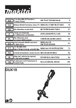
Figure 40. Placement of the insert before fixing in the pressure bar
Danger!
Risk of injury!
In order to mount the insert in the pressure bar:
8.3.1 Put the insert 1 (Fig. 41) under the pressure beam so that the insert pins are
under the holes in the pressure beam.
8.3.2 Pressing pedal 2 (Fig. 41), bring the pressure beam down so that the insert pins
hit the holes in the beam and the insert adheres the entire surface to the bottom
surface of the beam.
8.3.3 Use a 3-mm hexagonal key with 3 mm to firmly screw in the screws 3 (Fig. 41)
into the threaded holes in the pressure bar, causing the insert to be blocked in the
clamping beam.
8.3.4 Release the pressure on the pedal 2 (Fig. 41) - the beam with the inserted insert
returns to the upper position
The removable insert must be attached under the front table! (Fig. 40).
The lack of the insert in the fixing place is treated by the programmer as if it was
mounted in the pressure bar and the minimum residue (waste) is greater.
Mounting the insert into the pressure bar causes;
the minimum chopping residue (waste) is 40mm (without insert 22mm),
maximum stack height is 76mm (without 80mm insert).
Содержание Cut-True 31H
Страница 1: ...Cut True 31H Guillotine Cutter OPERATOR MANUAL Second Edition 8 2019 ...
Страница 2: ......
Страница 26: ...Figure 26 Figure 27 ...
Страница 38: ...57 Figure 41 Operating elements used when mounting the insert in the pressure bar ...
Страница 43: ...62 Figure 44 Cover for the backgauge 1 and lead screw 2 Figure 45 Base frame covers ...