GLADIUS SMART System manual version 1.4
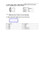
The definition of pin1 , pin 2 and pin4 are depending on jumper setting from
JCOM4 and
VFD_JR1
D. USB 2.0/1.1 Port
E. COM2
F. VGA
G. USB_LAN1 (LAN connector RJ45+USB 2.0/1.1 Port)
COM4_USB1
USB_LAN1
Pin
Definition
1
USB 5V
2
D-
3
D+
4
GND
COM2
Pin
Definition
1
DCD
2
RXD
3
TXD
4
DTR
5
GND
6
DSR
7
RTS
8
CTS
9
RI/ 5V /12V
VGA
Pin
Definition
1
RED
2
GREEN
3
BLUE
4
NC
5
GND
6
GND
7
GND
8
GND
9
VCC 5V
10
GND
11
NC
12
DDC Data
13
H-SYNC
14
V-SYNC
15
DDC Clock
Содержание Gladius Smart FH-5251
Страница 8: ...Detachable Stand Optional LCM Gladius Smart with VFD Gladius Smart with 2nd Display...
Страница 10: ...GLADIUS SMART Dimension...
Страница 27: ...Step 6 Select Auto detect Elo devices and click Next Step 7 Click Calibrate Elo Touchscreen monitors...
Страница 33: ...After the system finish rebooting follow the directions to calibrate the Touch screen...


