background image


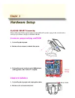
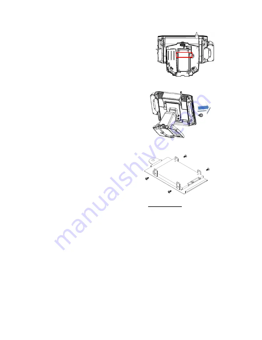
3.  Change the adapter under the terminal and beware of the direction


4.  Fix with a iron kit and one screw


5.  Link the DC power connector to terminal


2.5” Hard Disk Drive Installation 


1.  Turn off system power 

2.  Open the cover on the left of terminal 

and turn off system power 

3.  Remove one screw 


4.  Pull out whole HDD bracket 

5.  Mount SATA HDD into the bracketed 

space with 4 screws provided. 

6.  Put the bracket back and lock back 

the screw 


Note: If the HDD does not work normally, please refer to troubleshooting 


Содержание Gladius Smart FH-5251

Страница 1: ...Us se er r s s M Ma an nu ua al l Gladius Smart 15 All in one POS PC M B FH 5251 Version 1 7 Copyright 2012 All rights reserved All other brand names are registered trademarks of their respective owne...

Страница 2: ...on provided in this manual is intended to be accurate and reliable However FIRICH ENTERPRISES CO LTD assumes no responsibility for its use nor for any infringements upon the rights of third parties wh...

Страница 3: ...on it Do not place anything over the power cord 10 All cautions and warnings on the equipment should be noted 11 If the equipment is not used for a long time disconnect it from the power source to avo...

Страница 4: ...ntains information protected by copyright No part of this manual may be photocopied or reproduced in any form without prior written consent from the manufacturer 2012 All rights reserved The software...

Страница 5: ...ion 14 1 Turn off system power and unplug the cable 14 2 Remove one screw and iron kit 14 3 Change the adapter under the terminal and beware of the direction 15 4 Fix with a iron kit and one screw 15...

Страница 6: ...ot Detect HDD 50 Touch Panel does not Work 50 ELO Touch Panel Cannot Calibrate Correctly 50 Second LCD Panel is Not Functioning Properly 51 PS 2 Keyboard is not functioning normally 51 MCR is not func...

Страница 7: ...ess a high capacity of data efficiently Housing The solid aluminum housing dissipates the heat inside the system and makes it a perfect fan less solution additionally it also assures the compliance to...

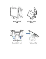
Страница 8: ...Detachable Stand Optional LCM Gladius Smart with VFD Gladius Smart with 2nd Display...

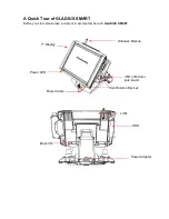
Страница 9: ...ADIUS SMART Before you start please take a moment to become familiar with GLADIUS SMART Identification Devices 1st Display Back I O VFD or Monitor pole stand Power LED HDD Wireless Module Power Adapte...

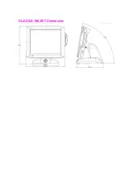
Страница 10: ...GLADIUS SMART Dimension...

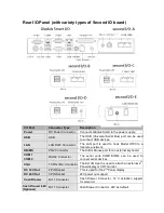
Страница 11: ...The K B or Mouse port for an external keyboard COM1 COM2 RS232 Connector The serial ports COM1 COM2 can be used to connect serial devices VGA 15 PIN VGA Connector The Ext VGA port is used to attach a...

Страница 12: ...2V 24V power out support Line Out Earphone Connector The audio port is for speakers Mic In Optional Microphone Connector This is used for allowing usage of microphone LPT1 26 PIN SCSI II Connector The...

Страница 13: ...es an introduction to Gladius Smart and this manual Chapter 2 Provides all necessary information for all hardware setup Chapter 3 Provides the necessary information for installing the Intel Chipset dr...

Страница 14: ...onnected when making any hardware changes to GLADIUS SMART Access to jumper setting and RAM 1 Turn off system power 2 Remove four screws to detach the panel 3 Pull up the panel and access to M B Jumpe...

Страница 15: ...Hard Disk Drive Installation 1 Turn off system power 2 Open the cover on the left of terminal and turn off system power 3 Remove one screw 4 Pull out whole HDD bracket 5 Mount SATA HDD into the bracke...

Страница 16: ...wer 2 The MCR socket can be found on the right side of terminal 3 Attach the MCR Assembly to terminal and connect the MCR cable to the MCR socket 4 Lock MCR to terminal with 2 screws Note If the MCR d...

Страница 17: ...pdf VFD Customer Display Installation 1 Turn off system power 2 Important make sure that the jumpers on the I O board are set correctly It s important to note that the supply voltage for the VFD custo...

Страница 18: ...drawer cable into cash drawer port Note If the cash drawer cannot be detected by the system please refer to troubleshooting Up to two cash drawers may be driven from this port Driving voltage of the...

Страница 19: ...m FEC Website Model A Please go to FEC website and download Gladius Smart AL 7435 driver B The installation sequence Chipset Driver VGA Driver LAN Driver Audio Driver Touch Driver Other Driver optiona...

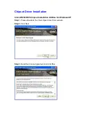
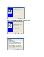
Страница 20: ...Driver Installation Intel ATOM D525 Chipset Installation Utilities for Windows XP Step 1 Please download the Intel chipset driver from website Step 2 Click Next Step 3 Read the License Agreement and c...

Страница 21: ...t and the drivers for the Intel Chip set will install Step 5 Please wait while the setup program processing Step 6 When the Setup COMPLETE message appears click Finish to restart your computer VGA Dri...

Страница 22: ...POSready 2009 the default setting is 800x600 with Clone mode if you need to use Extension Mode please set the 2nd panel as primary as below Warning After you set the panel to Extension Mode it won t...

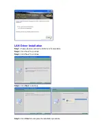
Страница 23: ...allation Step 1 Please double confirm the LAN driver from website Step 2 Click Next to continue Step 3 Click Next to continue Step 4 Click Next to continue Step 5 Click Finish to complete the installa...

Страница 24: ...Audio Driver Installation Step 1 Please download the Audio driver from website Step 2 Click Next to continue Step 3 Click Next to continue...

Страница 25: ...ick Finish and restart the system ELO Touch Installation Step 1 Please double confirm the ELO driver from website Step 2 Click OK to continue unzip the driver for latest version please reference to FE...

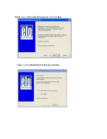
Страница 26: ...Step 3 Install Elo Touch drivers and utilities Step 4 Tick the Install USB Touchscreen Drivers and click Next to continue Step 5 Read the License Agreement and click Yes if you accept it...

Страница 27: ...Step 6 Select Auto detect Elo devices and click Next Step 7 Click Calibrate Elo Touchscreen monitors...

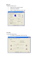
Страница 28: ...e the touch screen Red bull s eye will pop up three time on different position ELO Control Panel This section explains the different options in the ELO control Panel General tab The General tab allows...

Страница 29: ...Mode tab allows you to Adjust all mouse emulation controls Change cursor properties Enable or disable right mouse button utility Sound tab The Sound tab allows you to To change sound properties for EL...

Страница 30: ...Properties tab The Properties tab allows you to View Controller Information About tab The About tab displays Information about ELO Touch systems...

Страница 31: ...TI TouchKit Tools Installation Step 1 Please double confirm the EETI driver downloaded from website Step 2 Click OK to continue unzip the driver Step 3 Open Setup exe Step 4 Click Next Step 5 Click Ne...

Страница 32: ...Step 6 Click OK to close the pop up dialog Step 7 Click Support Multi Monitor System and then Next to continue Step 8 Click Next Step 9 Click OK and turn off the computer to restart your system again...

Страница 33: ...After the system finish rebooting follow the directions to calibrate the Touch screen...

Страница 34: ...the different options in the TouchKit control Panel General tab The general tab allows you to Manage the touch screen controller you installed Tools tab The tools tab allows you to Calibrate the touch...

Страница 35: ...ss LAN Driver Installation Step 1 Please double confirm the Wireless LAN driver from website Step 2 Click Next to continue Step 3 Select Install driver and Ralink WLAN Utility Step 4 Select Ralink Con...

Страница 36: ...GLADIUS SMART System manual version 1 4 Step 5 Select Install to continue Step 6 Select Finish to complete the installation...

Страница 37: ...100K hrs Option CCFL 1024 x 768 30K hrs Brightness 450 nits Option 250 nits Touch Screen 5w Resistive touch Serial Port 2 x COM ports DB 9 male 1 x COM port RJ 45 for Customer display Option 2 x COM...

Страница 38: ...anless Thermal Design Operating Temperature 0 40 O S Supported Windows XP Pro Embedded WEPOS POS Ready2009 Win 7 Dimensions W x H x D 258 61mm x 358 11mm x 269 31mm EMI Safety CE FCC RoHS I O Pin Defi...

Страница 39: ...1 1 Port E COM2 F VGA G USB_LAN1 LAN connector RJ45 USB 2 0 1 1 Port COM4_USB1 USB_LAN1 Pin Definition 1 USB 5V 2 D 3 D 4 GND COM2 Pin Definition 1 DCD 2 RXD 3 TXD 4 DTR 5 GND 6 DSR 7 RTS 8 CTS 9 RI...

Страница 40: ...ot Transmitting Activity LED Pin Definition 1 Data 0 2 Data 0 3 Data 1 4 Data 1 5 Data 2 6 Data 2 7 Data 3 8 Data 3 LPT Pin Definition Pin Definition 1 STB 14 AFD 2 PD0 15 ERR 3 PD1 16 INIT 4 PD2 17 S...

Страница 41: ...al version 1 4 J RJ11 Port K AUDIO_JACK Audio Line Out Jumper Setting RJ11 Pin Definition 1 GND 2 GPIO 0 3 CASH Drawer Switch 4 12V 5 GPIO 1 6 GND Audio Jack Pin Definition 1 GND 2 Line Out L 3 AUDIO_...

Страница 42: ...al use This connector is reserved for future use 2 CPU_FAN CPU FAN 3 SYS_FAN System FAN CPU_FAN Pin Definition 1 GND 2 12V RPM control 3 RPM detect 4 RPM control SYS_FAN Pin Definition 1 GND 2 12V RPM...

Страница 43: ...5V selection 6 INV_BRIG1 Inverter with Box header 7 LVDS 18 bit Connector KB_MS2 Pin Definition 1 GND 2 KDAT 3 F_KDAT 4 KCLK 5 F_KCLK 6 5V LVDS_PWR1 Default 1 2 Pin Definition 1 3 3V 2 DC input 3 5V I...

Страница 44: ...Data0 20 Backlight 5V 10 NC 21 LVDS Clock 11 Data0 22 Backlight 5V 8 JRS1 JRS2 JRS3 JRS4 JRS5 Only COM2 available for RS232 RS422 or RS485 selections JRS2 JRS3 JRS4 JRS5 Default 1 2 Pin Definition 1...

Страница 45: ...2 PS JCOM4 is pre set as 5 6 short for 12V customer display JCOM6 is pre set as 1 2 short for 5v built in LCM display 10 COM1 COM3 COM5 COM6 Serial Port with Box header Pin Definition Pin Definition...

Страница 46: ...ignal for PIN4 of COM4 port 5 RI4 1_5V 12V_F 6 GND PS JCOM4 is set to 5 6 short for 12V VFD display as default VFD Mode VFD_JR1 1 2 3 5 4 6 Short JCOM4 5 6 Short RS232 Mode VFD_JR1 1 3 2 4 Short JCOM4...

Страница 47: ...GND 5 LAN Action LED 6 Stand by 5V 7 HDD LED 8 VCC 5V 9 System Reset 10 GND 13 F_USB1 F_USB2 USB Pin header Pin Definition Pin Definition 1 USB Power 5V 2 USB Power 5V 3 USB Dx 4 USB Dy 5 USB Dx 6 US...

Страница 48: ...and by 5V 15 F_AUDIO Front Audio Box header Pin Definition Pin Definition 1 Amplifier Out_R 2 MIC_L 3 Amplifier Out_R 4 MIC_R 5 GND 6 Line In_R 7 Amplifier Out_L 8 Line In_L 9 Amplifier Out_L 10 Line...

Страница 49: ...Definition 1 GND 2 Battery 3V 3 Battery 3V 18 SATAPW_1 SATAPW_2 SATA HDD Power 5V 12V Pin Definition 1 12V 2 GND 3 GND 4 5V 19 LCDPWR_CON LCD Power ON OFF 20 BKLTEN_CON Back light Inverter Enable Disa...

Страница 50: ...uld be defective B HDD power cable is not connected properly to the mainboard or it could be defective C Check CMOS setup set SATA HDD to Auto detects Touch Panel does not Work A Check if the ELO driv...

Страница 51: ...ght if the is inverter is defective C Check the 10 PIN VGA cable is well connected to main board VGA2 D The main board VGA chip could be defective PS 2 Keyboard is not functioning normally A Make sure...

Страница 52: ...could be defective LAN is not functioning properly A Check if the LAN driver is installed properly Please refer to the LAN driver installation B Check if there are any IRQ conflicts C Check if the RJ4...

Отзывы: