© 2020 Carrier
54
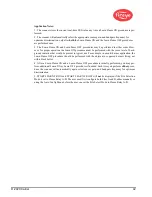
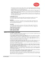
Each upward step in the User Gain setting will increase the Signal Strength number for the sensor
by approximately 50%. Each downward step in the User Gain setting will decrease the Signal
Strength number for the sensor by approximately 33%.
Example 1: Assume that you observe a Signal Strength of "080" when the User Gain setting is 12.
If you then increase the User Gain setting from 12 to 13 you should expect to see the Signal Strength
increase to approximately "120".
Example 2: Assume that you observe a Signal Strength of "240" when the user Gain setting is 20.
If you then decrease the User Gain setting from 20 to 19 you should expect to see the Signal Strength
decrease to approximately "160".
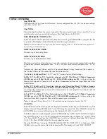
A-FEG LRNED (LEARNED)
The Front End Gain value stored when LEARN ON was performed. Possible values (5-255).
The current real time FEG value is displayed on the far left position of the bottom row.
A-MIN FEG
If the real-time Front End Gain value falls below this setting, the flame signal will be driven
to zero. Possible values (5-255), default (5). The current real time FEG value is displayed on
the far left position of the bottom row.
A-MAX FEG
If the real-time Front End Gain rises above this setting, the flame signal will be driven to
zero. Possible values (5-255), default (255). The current real time FEG value is displayed on
the far left position of the bottom row.
SELECT to Exit to Previous Menu
Return to Main CONFIG Menu
SELECT to Exit BACK to MAIN
Returns to Main Status Menu
MANUAL SET-UP IN MANUAL CONFIG MENU
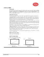
In Manual Configuration, the user may set values for t h e G A I N R A N G E , BAND (Freq), User
Gain (1-31), FEG Learned, FEG Min and FEG Max.
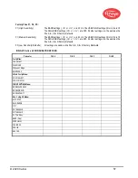
In the Manual Config Menu with the target flame ON
(at low fire), record the sensor signal
strength and stability at each of the 21 modulation BANDS: 23, 31, 39, 46, 54, 62, 70, 78, 85, 93,
101, 109, 117, 125, 132, 140, 148, 156, 164, 171 and 179 Hz. The signal strength range is 0-999. It
may be necessary to adjust the sensor GAIN in order to keep the signal strength value on scale. If so,
observe and record the sensor GAIN value (1-31) selected.
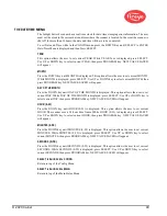
In the Manual Config Menu with the target flame OFF
(leaving other burners firing), observe and
record the sensor signal strength and stability at each of the twenty-one modulation BANDS: 23,
31, 39, 46, 54, 62, 70, 78, 85, 93, 101, 109, 117, 125, 132, 140, 148, 156, 164, 171 and 179Hz.
Do not
adjust the sensor USER GAIN at this time.
At each of the twenty-one BAND settings, compare the recorded Flame ON signal strength to
the recorded Flame OFF signal strength.
Select the BAND setting that yielded the greatest Flame
ON to Flame OFF signal ratio and the greatest stability.
Adjust the sensor gain
(1-31) so that the flame ON signal strength is well above the flame relay ON
THRESHOLD, and the flame OFF signal strength is well below the flame relay OFF THRESHOLD
(see “Flame Relay Thresholds”).
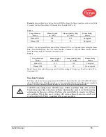
Note: For best scanner operation, the Flame ON Signal Strength should be between 100 and
150 or higher even though the Flame Quality display is capped at 100.
Each upward step in the User Gain setting will increase the Signal Strength number for the sensor by
approximately 50%. Each downward step in the User Gain setting will decrease the Signal Strength
number for the Sensor by approximately 33%.
Содержание InSight 4 Series
Страница 19: ... 2020 Carrier 19 Figure 14 WIRING DIAGRAM 95UVS4 1 95IRS4 1 with 59 547 cable ...
Страница 27: ... 2020 Carrier 27 THE MAIN STATUS MENU FIGURE 20 MAIN STATUS MENU LOOP ...
Страница 36: ... 2020 Carrier 36 THE CONFIG MENU FIGURE 23 CONFIG MENU LOOP ...
Страница 40: ... 2020 Carrier 40 THE AUTO CONFIG MENU FIGURE 25 AUTO CONFIG MENU LOOP ...
Страница 43: ... 2020 Carrier 43 THE FILE COPY MENU FIGURE 26 FILE COPY MENU LOOP ...
Страница 45: ... 2020 Carrier 45 THE 4 20 mA MENU FIGURE 27 4 20mA MENU LOOP ...
Страница 47: ... 2020 Carrier 47 THE DATE TIME MENU FIGURE 28 DATE TIME MENU LOOP ...
Страница 49: ... 2020 Carrier 49 THE COMMS MENU FIGURE 29 COMMS MENU ...
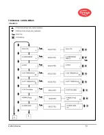
Страница 51: ... 2020 Carrier 51 THE MANUAL CONFIG MENUS FIGURE 30 ...
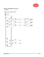
Страница 52: ... 2020 Carrier 52 MANUAL CONFIG MENUS continued FIGURE 31 ...


