© 2020 Carrier
15
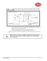
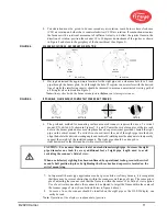
FIGURE 11.
SWIVEL MOUNT
BALL
FIELD OF VIEW
ORIFICE
PURGE
AIR SUPPLY
ORIFICE RETAINER
3/8” PLUG
FIELD OF VIEW
1" SWIVEL MOUNT
60-1199-1, 2 SEALING COUPLING
ELECTRICAL ACCESSORIES
(see note)
Note: Hazardous Area requirements for InSight Series 4scanners with electrical
connectors:
1.
For hazardous locations, either the set screw must be tightened (if provided) or the plastic “Lok
Fast” retainer (if provided) with the 59-547-xx must be installed over the quick disconnect
connector.
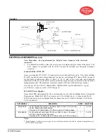
Scanner Cables, P/N 59-547
Fireye recommends P/N 59-547 (12-conductor) color-coded multi-core cable. This cable includes
18 AWG conductors and a flame-retardant, low smoke, zero halogen PVC jacket. Refer to page 10
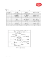
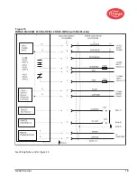
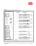
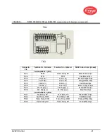
for full cable specifications. Refer to figure 12, 14, 15 and 16 for color code and connection
information. This raw-stock cable is used as extension wiring between a junction box and the burner
management system. The maximum total cable length is 1000 feet (305 meters) per scanner.
Note: Model 95UVS4-1WINC, 95IRS4-1WINC, 95IRS4E-1WINC, and 95UVS4E-1WINC require
p/n 59-608 (12-conductor) cable (59-497 Insight 1).
24 Volt DC Power Supplies
Fireye offers DIN rail mounted 24 Vdc power supplies for use with the InSight Series 4 Integrated
flame scanner. Model 60-2685-25 can power up to five InSight Series 4 scanners and the 60-
2685-50 can power up to ten InSight Series 4 scanners (see note 1). Refer to bulletins CU-100 and
CU-118 for details.
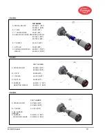
PART NUMBER
DESCRIPTION
NOTES
BULLETINS
60-2685-25
24 Vdc Switching Power Supply, 100-240 vac 50/60 Hz. input, 2.5 A output at
24 Vdc. Powers up to five scanners.
Dimensions: 3.7"(95mm) high x 1.6" (40mm) wide x 4.3"(108mm) deep
1
CU-118
60-2685-50
24 Vdc Switching Power Supply, 100-240 vac 50/60 Hz. input, 5.0A output
at 24 Vdc. Powers up to ten scanners.
Dimensions: 4.5" (115mm) high x 2.0" (50mm) wide x 4.8" (121mm) deep.
1
CU-118
Notes:
1. Listed output is when power supply is vertically mounted, and with an ambient temperature of
104°F (40°C) maximum.
Содержание InSight 4 Series
Страница 19: ... 2020 Carrier 19 Figure 14 WIRING DIAGRAM 95UVS4 1 95IRS4 1 with 59 547 cable ...
Страница 27: ... 2020 Carrier 27 THE MAIN STATUS MENU FIGURE 20 MAIN STATUS MENU LOOP ...
Страница 36: ... 2020 Carrier 36 THE CONFIG MENU FIGURE 23 CONFIG MENU LOOP ...
Страница 40: ... 2020 Carrier 40 THE AUTO CONFIG MENU FIGURE 25 AUTO CONFIG MENU LOOP ...
Страница 43: ... 2020 Carrier 43 THE FILE COPY MENU FIGURE 26 FILE COPY MENU LOOP ...
Страница 45: ... 2020 Carrier 45 THE 4 20 mA MENU FIGURE 27 4 20mA MENU LOOP ...
Страница 47: ... 2020 Carrier 47 THE DATE TIME MENU FIGURE 28 DATE TIME MENU LOOP ...
Страница 49: ... 2020 Carrier 49 THE COMMS MENU FIGURE 29 COMMS MENU ...
Страница 51: ... 2020 Carrier 51 THE MANUAL CONFIG MENUS FIGURE 30 ...
Страница 52: ... 2020 Carrier 52 MANUAL CONFIG MENUS continued FIGURE 31 ...


