background image

© 2020 Carrier 

53 

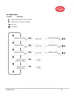
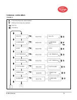
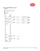
THE MANUAL  CONFIG MENU

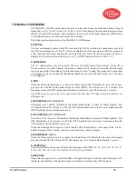
The MANUAL CONFIG menu allows the user to select and change the following settings for each 
flame file (A, B, C, or D): Active File (A, B, C, or D), Gain Range, Flame-Failure-Response-Time 
(FFRT), On and Off Thresholds, On-Time Delay, the sensors Flame Flicker Frequency (BAND) and 
Users Gain, and the sensor's Front-End-Gain (FEG) settings. 

The following descriptions refer to the MANUAL CONFIG menu. 

ACTIVE FILE

The user can manually choose which file to run (and to Edit) by selecting this menu choice provided 
the File Select setting is set to “KEY” (refer to Config Menu). If the user wants to Edit the contents of 
a file, they must first select and run that particular file. The active file that this option will affect is 
displayed in the first position of the top row (e.g., A-FFRT) indicates the active file is “A”). 

A-GAIN RANGE

The  “A”  indicates the  active file  selected. There are  selectable internal “gain ranges” for  the  IR or 
UV sensor Gain.  If, when “Aiming” the scanner, a number of 24 or higher is observed, then the signal 
is over-range and the “Gain Range” should be reduced. If, when “Aiming” the scanner, an Aim number 
of less than 10 is observed, then the Gain Range should be increased. Allowable values are: 1 (Lowest) 
to 10 (Highest). 

A-FFRT

When the Flame Quality drops to or below the Flame Relay OFF Threshold, the relay will de-ener- 
gize  after  the  selected Flame Failure Response Time (FFRT). The  choices are  1  to  6  seconds. The 
maximum 

allowable 

FFRT setting is determined by local safety code. The default is 1 second. 

Any FFRT selection greater than 4 seconds violates the FM Class 7610 Approval and is therefore not 
FM Approved.

A-ON THRESHLD (ON THRESHOLD)

This refers to the “pull-in” threshold of the internal Flame Relay, in terms of “Flame Quality”. The 
ON Threshold can be set from 5 to 100. The ON Threshold must be at least 5 units higher than the 
OFF Threshold. Factory default value is 40. 

A-OFF THRESHLD (OFF THRESHOLD)

This refers to the “drop-out” threshold of the internal Flame Relay, in terms of “Flame Quality”. The 
OFF Threshold can be set from 0 to 95. The OFF Threshold must be at least 5 units lower than the 
ON Threshold. Factory default value is 20. 

When the Flame Quality is equal to or less than the OFF Threshold (for a time equal to the “Flame 
Failure Response Time” setting, see below), the flame relay will de-energize. 

A-ON TIME DELAY (DELAY)

When  the  Flame Quality rises  to  or  above  the  Flame  Relay  ON  Threshold, the  relay  will  energize 
after the selected On Time Delay (OTD). The choices are 1 to 6 seconds. The default is 1 second. 

A - BAND (Freq)

There are twenty-one choices of flame-flicker-frequencies (BANDS): 23, 31, 39, 46, 54, 62, 70, 78, 
85, 93, 101, 109, 117, 125, 132, 140, 148, 156, 164, 171 and 179Hz. 

A-USER GAIN

Adjust the sensor gain (1-31) so that the flame ON signal strength is well above the flame relay ON 
threshold, and the flame OFF signal strength is well below the flame relay OFF threshold. 

Содержание InSight 4 Series

Страница 1: ...eted flame During the scanner set up procedure the modulation frequency that yields the best flame ON OFF discrimination is selected The appropriate modulation frequency and sensor gain can be either manually or automatically selected InSight Series 4 is a solid state detector scanner utilizing either UV or IR detector and two different available connectors which are compatible either with the 59 ...

Страница 2: ...ate this equipment all relevant sections of this document must be read and fully understood If in doubt about any requirements consult Fireye Installation commissioning or adjustment of this product MUST be carried out by suitably trained engineers or personnel qualified by training and experience After installation or modifications to the installation all functions of the equipment MUST be checke...

Страница 3: ... 22 WIRING FOR REMOTE COMMUNICATIONS 23 GROUNDING AND SHIELDING TECHNIQUES 24 PROGRAMMING THE INSIGHT Series 4 SCANNER 24 INSIGHT Series 4 MENU STRUCTURE 25 THE MAIN STATUS MENU 27 THE ERROR HISTORY MENU 31 THE PASSWORD MENU 34 THE CONFIG MENU 36 THE AUTO CONFIG MENU 40 THE FILE COPY MENU 43 THE 4 20 mA MENU 45 THE DATE TIME MENU 47 THE COMMS MENU 49 THE MANUAL CONFIG MENUS 51 MANUAL SET UP IN MAN...

Страница 4: ...nergizes its normally open contacts closed when the flame quality is at or above the programmed flame ON threshold and remains on until the flame quality is at or below the programmed flame OFF threshold IMPORTANT NOTE The FAULT RELAY is energized when the scanner is powered 24 V DC and when the scanner has successfully passed all internal self checking routines The Fault relay is de energized if ...

Страница 5: ...alarm relay operation Restore power to the scanner 4 Remove the bypass and otherwise restore normal operation The suggested proof test interval and good practice is to carry out the proof test annually The above covers the suggested proof test procedures and periodic proof test requirements in terms of IEC61508 This should not be considered a replacement for recommended testing of the scanner adju...

Страница 6: ...s 21 21 21 21 21 21 21 21 Memory Files 4 4 4 4 4 4 4 4 Communications YES YES YES YES YES YES YES YES Auto Config YES YES YES YES YES YES YES YES 2 X 16 Alpha Display YES YES YES YES YES YES YES YES Housing Material Aluminum Aluminum Aluminum Aluminum Aluminum Aluminum Aluminum Aluminum DIMENSIONS FIGURE 1 SCANNER 95UVS4 1WINC 95UVS4E 1WINC 95IRS4 1WINC 95IRS4E 1WINC 95UVS4 1 95IRS4 1 Scanner Type...

Страница 7: ...SP Suitably rated blanking elements must be used on all unused openings Supply connection wiring shall have a temperature rating of at least 105 C Note The above items are suitable for the InSight Series 4 scanners rated environment and conditions of use Warning Risk of electrostatic discharge Make sure that all personnel and equipment are correctly grounded when installing or handling the InSight...

Страница 8: ... YES YES YES YES 95UVS4 1CEX UV SCREW TERMINAL YES YES YES YES 95IRS4 1CEX IR SCREW TERMINAL See note 2 YES YES YES YES 95UVS4 2CEX UV SCREW TERMINAL YES YES YES 95IRS4 2CEX IR SCREW TERMINAL YES YES YES 60 2984 1 UV SCREW TERMINAL 60 2984 2 IR SCREW TERMINAL 60 2984 3 UV SCREW TERMINAL 60 2984 4 IR SCREW TERMINAL Notes 1 UL Hazardous Locations ATEX DEMKO 18 ATEX 2039X II 3 G Ex ic nA nC IIC T5 Gc...

Страница 9: ... BSP female pipe mount with 3 8 BSP female cooling air connection OPTIONAL MOUNTING FLANGE CAST ALUMINUM Material Cast aluminum without heat insulating thread insert with grey polyester powder coat finish Flange Threads P N 60 2692 1 NPT female pipe mount with 3 8 NPT female cooling air connection P N 60 2693 1 BSP female pipe mount with 3 8 BSP female cooling air connection ELECTRICAL Input Power...

Страница 10: ...ow and furnace loads ranges of fuel firing Rejection of the ignitor flame if too short or in the wrong position to ignite the main flame reliably thus prohibiting the delivery of fuel to the burner INSTALLATION PROCEDURE WARNING Protective filtered lenses should be worn when viewing flame Infrared and ultraviolet energy from the flame can be damaging to the eyes 1 The best results are obtained whe...

Страница 11: ...te and secure using three hexed cap screws not provided Install the sight pipe on the swivel mount If a swivel is not used insert the end of the sight pipe into the hole align the hole to the desired viewing angle and tack weld welding must be adequate to temporarily support the weight of the installed scanner The sight pipe should be arranged to slant downward so that dirt and dust will not colle...

Страница 12: ...P N 60 2919 1 1 NPT female pipe mount with 3 8 NPT female cooling air connection P N 60 2919 2 1 BSP female pipe mount with 3 8 BSP female cooling air connection Optional Cast aluminum with grey polyester powder coat finish Does not contain heat insulating insert P N 60 2692 4 1 NPT female pipe mount with 3 8 NPT female cooling air connection P N 60 2693 4 1 BSP female pipe mount with 3 8 BSP fema...

Страница 13: ...UG 35 202 NPT G SURFACE MOUNTING 60 2919 1 1 NPT FLANGE 60 2919 2 1 BSP FIGURE 7 FIGURE 8 A SWIVEL MOUNT PART NUMBER 60 1664 3 NPT 60 1664 4 BSP B 1 WYE 35 200 NPT C 1 NIPPLE 35 127 2 NPT D 3 8 PLUG 35 202 NPT E SURFACE MOUNTING FLANGE 60 2919 1 1 NPT 60 2919 2 1 BSP A SWIVEL MOUNT PART NUMBER 60 1664 3 NPT 60 1664 4 BSP B 1 NIPPLE 35 127 2 NPT C 3 8 THREAD OPENING D SURFACE MOUNTING FLANGE 60 291...

Страница 14: ...34 181 Complete set 53 121 ORIFICES Figure Qty Part Number Description 10 1 53 121 Orifice Kit Contains following items 10 1 53 121 2 Orifice Diameter 0 062 10 1 53 121 3 Orifice Diameter 0 078 10 1 53 121 4 Orifice Diameter 0 093 10 1 53 121 5 Orifice Diameter 0 109 10 1 53 121 6 Orifice Diameter 0 125 10 1 53 121 7 Orifice Diameter 0 187 10 1 53 121 8 Orifice Diameter 0 250 10 1 53 121 9 Orifice...

Страница 15: ...the burner management system The maximum total cable length is 1000 feet 305 meters per scanner Note Model 95UVS4 1WINC 95IRS4 1WINC 95IRS4E 1WINC and 95UVS4E 1WINC require p n 59 608 12 conductor cable 59 497 Insight 1 24 Volt DC Power Supplies Fireye offers DIN rail mounted 24 Vdc power supplies for use with the InSight Series 4 Integrated flame scanner Model 60 2685 25 can power up to five InSi...

Страница 16: ...ters 98 feet 5 inches 59 547 45 12 Conductor 45 meter cable assembly with 12 pin female connector 45 meters 147 feet 7 inches 59 547 60 12 Conductor 60 meter cable assembly with 12 pin female connector 60 meters 196 feet 10 inches 59 547 90 12 Conductor 90 meter cable assembly with 12 pin female connector 90 meters 295 feet 3 inches 59 547 12 Conductor cable without connector Sold by the foot for ...

Страница 17: ...pply Yellow Black stripe 3 Fault Relay Fault Relay Red Black stripe 4 4 20mA 4 20mA Red White stripe 5 RFS1 RFS1 Blue Black stripe 6 RFS2 Flame Relay NC Black Yellow stripe 7 Comm A Comm A Brown Orange stripe 8 Comm B Comm B Orange Black stripe 9 4 20mA 4 20mA Black Orange stripe 10 Fault Relay Fault Relay Brown Black stripe 11 Flame Relay NO Flame Relay NO Violet White stripe 12 Flame Relay Commo...

Страница 18: ... 2020 Carrier 18 Figure 13 WIRING DIAGRAM 95UVS4 1WINC 95IRS4 1WINC with 59 608 cable See Wiring Notes under Figure 15 ...

Страница 19: ... 2020 Carrier 19 Figure 14 WIRING DIAGRAM 95UVS4 1 95IRS4 1 with 59 547 cable ...

Страница 20: ...er s 4 20 mA output is internally powered and must be connected to a passive voltage free device Do not connect to an externally powered 4 20 mA loop or the scanner may be damaged 9 The return for the customer s 4 20 ma device may be connected to either scanner pin B 2 or pin H 9 11 The following peripherals must be SELV PELV by an approval according to DIN EN 60950 or an external isolator must be...

Страница 21: ...1 3 Comm A Comm A Brown Orange stripe TB1 4 Comm B Comm B Orange Black stripe TB1 5 4 20mA 4 20mA Red White stripe TB1 6 4 20mA 4 20mA Black Orange stripe TB1 7 24V Supply 24V Supply Yellow Black stripe TB1 8 24V Supply 24V Supply Blue Red stripe Terminal Block 2 TB2 TB2 1 Fault Relay NC Fault Relay NC Brown Black stripe TB2 2 Fault Relay COM Fault Relay COM Red Black stripe TB2 3 Flame Relay COM ...

Страница 22: ...Closed C Closed Closed D The default is RFS Key Pad which allows manual file selection at the scanner keypad only The user may also select RFS Comms which will allow manual selection at a remote computer running Fireye software Fireye recommends the use of shielded cable for the two remote file select switches or relays The switch contacts should be rated for low current operation 3mA dc The InSig...

Страница 23: ...urner management system For wiring distances when the InSight Series 4 scanner to the control room is greater than 200 feet remote communications requires wiring a twisted shielded pair of wires in a multi drop wiring configuration If communications problems occur use a terminating resistor at the scanner located farthest from the communication source Note The maximum distance for the communicatio...

Страница 24: ...nners wired in a multi drop configuration Belden 9841 using wiring harness or junction box Connect braided shield of 59 547 or 59 608 for 1WINC to earth ground at power supply Twist together and tape to electrically isolate shield drains from Belden 9841 cables inside each wiring harness or junction box Connect to earth ground at RS485 source e g IBM computer PROGRAMMING THE INSIGHT Series 4 SCANN...

Страница 25: ...ints for the InSight Series 4 scanner The Config menu is entered from the Main menu after first entering a four digit password Default is 0205 From the CONFIG menu the user can enter the AUTOMATIC CONFIG and MANUAL CONFIG and other menus 3 AUTOMATIC CONFIG MENU From the Automatic Config Menu the user views the flame signal intensity while physically aiming the scanner for optimum signal With the t...

Страница 26: ...MODE Pg 28 37 Auto FSLCT Delay Pg 37 PASSWORD Pg 33 Reset MAX Temp N FS Squelch Msgs Do Not Display Pg 37 Active file A Pg 37 A UV IR gain range 10 Pg 37 4 20 mA Settings Pg 38 45 DATE TIME Pg 38 47 COMMS SETTINGS Pg 38 49 MANUAL CONFIG Pg 38 50 Select to Exit Back to Main Pg 38 CONFIG MENU Pg 35 PASSWORD MENU Pg 38 49 ERROR HISTORY MENU Pg 26 29 MAIN STATUS MENU Pg 26 ...

Страница 27: ... 2020 Carrier 27 THE MAIN STATUS MENU FIGURE 20 MAIN STATUS MENU LOOP ...

Страница 28: ...he Flame Signal number but is capped at 100 Example If flame signal strength is displayed as FS 085 the Flame Quality number would be displayed as FQ 085 If flame signal strength is displayed as FS 174 the Flame Quality number would be displayed as FQ 100 Flame Quality The Flame Quality number FQ xxx can range from 0 to 100 The Flame Quality number is determined by the flame signal strength of the...

Страница 29: ...two scanners in a communications loop should have the same address Default comm values are 247 19200 8 N 1 indicating address 247 19200 baud 8 bits No parity 1 stop bit Flame Relay Threshold The flame relay has a factory programmed FLAME ON threshold of 40 and a FLAME OFF threshold of 20 0 100 scale Other ON and OFF thresholds may be programmed to suit particular applications On Threshold Flame ON...

Страница 30: ...e real time FEG is now 40 indicating a dimmer flame the scanner will decrease the Flame Quality number by 50 20 40 However if the Learned FEG value was 20 and the real time FEG is now 10 indicating a brighter flame the Flame Quality number will not be affected Select To Enter Error History Press Select Key to enter the Error History screen to view error status and codes The most recent Error is di...

Страница 31: ... 2020 Carrier 31 THE ERROR HISTORY MENU FIGURE 21 ERROR HISTORY MENU LOOP Keypad Legend UP Key Scrolls through menu counter clockwise DOWN Key Scrolls through menu clockwise SELECT Key ...

Страница 32: ...ttern will be repeated until the abnormal condition no longer exists or until the user depresses any key If the user depresses any key the warning message will be suppressed for thirty 30 seconds Group I Warning Messages Always Active Warning Message Condition Effect TOO COLD 40C Currently xxC FLAME SIGNAL SET TO 0 The scanner s internal temperature has fallen to 40C 40F or below Note There is a 2...

Страница 33: ...CH UV SIGNAL The flickering AC component of the UV source is too strong The scanner cannot properly detect the flame flicker See note 3 The UV flame signal will become erratic or go to zero Notes 1 Group II Warning messages are suppressed whenever Do NOT Display is selected under the FS Squelch Msgs parameter in the CONFIG menu This is the default setting Although the message will be suppressed if...

Страница 34: ...ord from the Configuration Menu In the first case the menu will appear as shown below In the Second case CHNGE replaces the word ENTER ENTER PW DIGIT 1 0xxx NOTE 1 Entry Aborted NOTE 2 ENTER PW DIGIT 2 02xx ENTER PW DIGIT 3 020x NOTES 1 User presses Up and Down keys to change the value of the displayed digit 2 Pressing the Program key enters the selected value and moves to the next digit ENTER PW ...

Страница 35: ... Press DOWN key once to PASSWORD If you wish to change the password at this time Press the SELECT key see the Change Password section below Otherwise depress the DOWN key to advance to the CONFIG menus Entering the correct Password allows the user 20 minute access to the CONFIG menus Saving any parameter will re start this 20 minute time out period When the user returns to the MAIN STATUS menu the...

Страница 36: ... 2020 Carrier 36 THE CONFIG MENU FIGURE 23 CONFIG MENU LOOP ...

Страница 37: ...2 of 2 A B From Config Menu Page 1 of 2 SELECT to Enter File Copy Menu SELECT to Enter 4 20mA Config Menu SELECT to Enter Date Time Menu SELECT to Enter COMMS SETTINGS SELECT to Enter Man Config FR SELECT to Exit BACK to MAIN To File Copy Menu To 4 20 mA Config Menu To Date Time Config Menu To Comms Menu To Manual FR Config MENU To Main Status Menu Page 45 Page 47 Page 49 Page 51 Page 53 Page 29 ...

Страница 38: ...nergized Allowable times are 0 60 seconds PASSWORD The user may change the password to any four digit code desired See Password Menu for details Reset Max Temp The user may reset the highest internal temperature value that the scanner has recorded The Max Temp will then be equal to the current internal temperature value FS Squelch Msgs Under certain operating conditions such as Front End Gain FEG ...

Страница 39: ...e the UP and DOWN arrows to scroll to the correct year Press PROGRAM to save this value Press DOWN arrow to view the MONTH To change the month value press SELECT scroll UP or DOWN to the correct MONTH and press PROGRAM Press DOWN arrow to DAY of the MONTH Press SELECT scroll to cur rent DAY and press PROGRAM to Save You can enter HOUR MINUTES SECONDS by follow ing the process outlined above If the...

Страница 40: ... 2020 Carrier 40 THE AUTO CONFIG MENU FIGURE 25 AUTO CONFIG MENU LOOP ...

Страница 41: ...ottom row The AIM value represents the flame flicker intensity of the flame for the entire flicker frequency spectrum as sensed by the UV sensor or IR sensor Run the flame at low fire rate and observe the signal intensity The AIM number should be at its peak highest numerically when the scanner is aimed at the primary combustion zone first 1 3 of the flame Aim the scanner at the first 1 3 of the f...

Страница 42: ...be present in typical use For example in a multi burner application the Learn Flame OFF procedure should be performed with the adjacent or opposed burners firing not with a black boiler 4 After a Learn Flame ON and a Learn Flame OFF procedure is initially performed you may per form additional Learn ON or Learn OFF procedures if needed Each time you perform either proce dure the scanner will automa...

Страница 43: ... 2020 Carrier 43 THE FILE COPY MENU FIGURE 26 FILE COPY MENU LOOP ...

Страница 44: ...t 23 Hz The IR or UV FEG LRNED settings are 255 At these settings the scanner will respond to flame but will not likely discriminate between the target flame and other nearby flames In File F2 the IR or UV User Gain values are set at 15 and the IR or UV flicker frequen cies BAND are set at 23 Hz The IR or UV FEG LRNED settings are 255 At these intermedi ate settings the scanner may not respond to ...

Страница 45: ... 2020 Carrier 45 THE 4 20 mA MENU FIGURE 27 4 20mA MENU LOOP ...

Страница 46: ...lame signal is 000 The range or Flame Signal value for 20 mA 20mA MAP VAL is user selectable anywhere between 400 and 999 The factory default is 999 If the user selects a MAP VAL of 500 when the Flame Signal reaches 500 the analog output will be at 20 mA Press SELECT to enter option and then use UP or DOWN key to pick MAP Value between 40 100 for FQ or between 400 999 for FS then press PROGRAM to ...

Страница 47: ... 2020 Carrier 47 THE DATE TIME MENU FIGURE 28 DATE TIME MENU LOOP ...

Страница 48: ...E MONTH is displayed This option allows the user to set current DAY While DAY OF THE MONTH is displayed press SELECT Use UP or DOWN key to select current DAY then press PROGRAM key NEW VALUE SAVED will appear HOUR 0 23 Press the DOWN key until HOUR 0 23 is displayed This option allows the user to set current HOUR The scanner uses a 24 hour time frame While HOUR 0 23 is displayed press SELECT Use U...

Страница 49: ... 2020 Carrier 49 THE COMMS MENU FIGURE 29 COMMS MENU ...

Страница 50: ... address Default factory address for InSight Series 4 is 247 MODBUS BAUD This option allows the user to set modbus communication baud rate Valid values are 4800 9600 19200 and the factory default baud rate is 19200 MODBUS PARITY This option allows the user to set communication parity Valid values are 8 N 1 8 E 1 8 N 2 8 O 1 Default factory parity is 8 N 1 SELECT to Exit BACK to CONFIG Return to to...

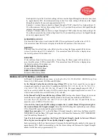
Страница 51: ... 2020 Carrier 51 THE MANUAL CONFIG MENUS FIGURE 30 ...

Страница 52: ... 2020 Carrier 52 MANUAL CONFIG MENUS continued FIGURE 31 ...

Страница 53: ...after the selected Flame Failure Response Time FFRT The choices are 1 to 6 seconds The maximum allowable FFRT setting is determined by local safety code The default is 1 second Any FFRT selection greater than 4 seconds violates the FM Class 7610 Approval and is therefore not FM Approved A ON THRESHLD ON THRESHOLD This refers to the pull in threshold of the internal Flame Relay in terms of Flame Qu...

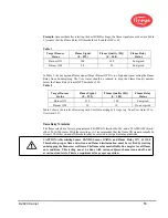
Страница 54: ...U In Manual Configuration the user may set values for the GAIN RANGE BAND Freq User Gain 1 31 FEG Learned FEG Min and FEG Max In the Manual Config Menu with the target flame ON at low fire record the sensor signal strength and stability at each of the 21 modulation BANDS 23 31 39 46 54 62 70 78 85 93 101 109 117 125 132 140 148 156 164 171 and 179 Hz The signal strength range is 0 999 It may be ne...

Страница 55: ... 23 to User Gain 19 Flame Relay Thresholds The flame relay has a factory programmed FLAME ON threshold of 40 and a FLAME OFF thresh old of 20 0 100 scale With these settings it is recommended that the flame ON signal normally be at least 150 Other on and off thresholds may be selected to suit particular applications CAUTION After selecting Sensor BANDS Sensor GAINS and Flame Relay ON OFF Threshold...

Страница 56: ...AIN 100 5 Date Time Menu YEAR 2017 2017 4095 MONTH JAN JAN FEB MAR APR MAY JUN JUL AUG SEP OCT NOV DEC DAY OF THE MONTH 01 01 31 dependent on current value of MONTH HOUR 0 23 00 00 23 MINUTES 0 59 00 00 59 SECONDS 0 59 00 00 59 COMMS SETTINGS Menu MODBUS ADDRESS 247 001 247 MODBUS BAUD 19200 4800 9600 19200 MODBUS PARITY 8 N 1 8 N 1 8 E 1 8 N 2 8 O 1 Man Config Menu ACTIVE FILE A A B C D UV or IR ...

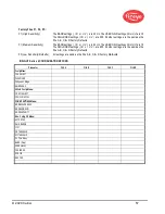
Страница 57: ...ED settings I R o r U V are 255 All other settings are the same as the File A B C D Factory Defaults F3 Low Sensitivity Defaults All settings are same as the File A B C D Factory Defaults INSIGHT Series 4 CONFIGURATION RECORD Parameter FILE A FILE B FILE C FILE D Config Menu FILE SELECT PASSWORD FS Squelch Msgs GAIN RANGE 4 20mA Config Menu FR 4 20 SELECT FR4 20 MAP VAL COMMS SETTINGS Menu MODBUS ...

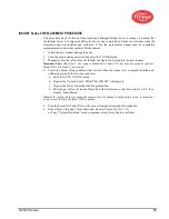
Страница 58: ...etect flame ON but may not properly indicate flame OFF until Step 4 is performed 4 Create the burner firing conditions that existed when the scanner was originally installed and calibrated typically the low fire condition a Enter the AUTO CONFIG menu b Depress the Up button until START LEARN ON is displayed c Depress the Select button then the Program button d The scanner will set its internal Fro...

Страница 59: ...is found defective in material or workmanship or which otherwise fails to conform to the description of the product on the face of its sales order THE FOREGOING IS IN LIEU OF ALL OTHER WARRANTIES AND FIREYE MAKES NO WARRANTY OF MERCHANT ABILITY OR ANY OTHER WARRANTY EXPRESS OR IMPLIED Except as specifically stated in these general terms and conditions of sale remedies with respect to any product o...

Отзывы: