© 2020 Carrier
24
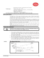
GROUNDING AND SHIELDING TECHNIQUES
FOR USE ON SCANNERS OR SCANNER CABLE LOCATED WITHIN 12" OF A HIGH
ENERGY OR HIGH VOLTAGE SOURCE.
1.
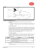
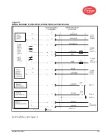
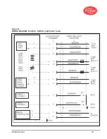
Connect a safety ground to scanner housing (Figure 13, 14 & 15).
2.
The scanner and scanner cable MUST be located at least 12" from the ignition source.
3.
Run a ground wire from the ignition transformer chassis to the ignitor assembly.
4.
Replace all frayed, cracked, or dirty (oily) ignition wire. Ignition wire must be in good working
condition.
5.
Electrically isolate the scanner from the burner using the surface mounting flange with integral
heat-insulating female thread insert.
6.
Cooling/Purge Air must be electrically isolated from the scanner (e.g. isolated short rubber
hose)
.
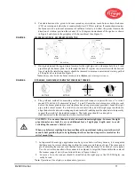
SCANNER TO CONTROL ROOM
SHIELDING TECHNIQUES
Scanner with scanner cables (59-547) wired directly
back to burner management system. See below for
remote communications.
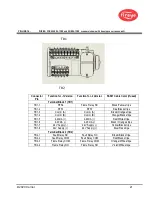
Connect braided shield of 59-547 or (59-608 for -1WINC) cable to earth ground at power
supply.
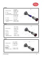
REMOTE COMMUNICATIONS: LESS THAN 200 FEET
Scanner with scanner cables (59-547)
wired directly back to control room.
Connect braided shield of 59-547 (or 59-608 for -1WINC) cable to earth ground at power
supply.
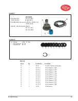
REMOTE COMMUNICATIONS: GREATER THAN 200 FEET
RS485 communications for scanners wired in a
multi-drop configuration (Belden 9841) using wiring
harness or junction box.
Connect braided shield of 59-547 (or 59-608 for -1WINC) to earth ground at power
supply. Twist together and tape (to electrically isolate) shield drains from Belden 9841
cables inside each wiring harness or junction box. Connect to earth ground at RS485
source (e.g. IBM computer).
PROGRAMMING THE INSIGHT Series 4 SCANNER
Keypad/Display:
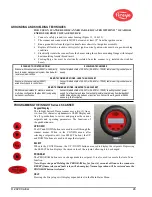
The InSight Series 4 flame scanner uses a two (2) line x
six- teen (16) character alphanumeric OLED Display and
five (5) pushbuttons to review and program the various
setpoints and operating parameters. The functions of
the pushbuttons are:
UP/DOWN
The UP and DOWN buttons are used to scroll through the
scanner menus. When in the CONFIG menu, after
selecting a setpoint to edit, (see SELECT button), the UP
and DOWN buttons are used to change that setpoint.
SELECT
When in the CONFIG menu, the UP / DOWN buttons are used to display the setpoints. Depressing
the SELECT button displays the stored value of the setpoint, allowing it to be changed.
PROGRAM
The PROGRAM button saves a change made to a setpoint. It is also used to execute the Auto Tune
function.
Note: Depressing and Holding the PROGRAM key for four (4) seconds will cause the scanner to
RESET (flame relays and fault relay will de-energize). Normal operation will be restored once the
PROGRAM button is released.
HELP
Pressing the Fireye logo will display expanded text in the Main Status Menu.
Содержание InSight 4 Series
Страница 19: ... 2020 Carrier 19 Figure 14 WIRING DIAGRAM 95UVS4 1 95IRS4 1 with 59 547 cable ...
Страница 27: ... 2020 Carrier 27 THE MAIN STATUS MENU FIGURE 20 MAIN STATUS MENU LOOP ...
Страница 36: ... 2020 Carrier 36 THE CONFIG MENU FIGURE 23 CONFIG MENU LOOP ...
Страница 40: ... 2020 Carrier 40 THE AUTO CONFIG MENU FIGURE 25 AUTO CONFIG MENU LOOP ...
Страница 43: ... 2020 Carrier 43 THE FILE COPY MENU FIGURE 26 FILE COPY MENU LOOP ...
Страница 45: ... 2020 Carrier 45 THE 4 20 mA MENU FIGURE 27 4 20mA MENU LOOP ...
Страница 47: ... 2020 Carrier 47 THE DATE TIME MENU FIGURE 28 DATE TIME MENU LOOP ...
Страница 49: ... 2020 Carrier 49 THE COMMS MENU FIGURE 29 COMMS MENU ...
Страница 51: ... 2020 Carrier 51 THE MANUAL CONFIG MENUS FIGURE 30 ...
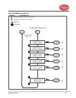
Страница 52: ... 2020 Carrier 52 MANUAL CONFIG MENUS continued FIGURE 31 ...

