background image

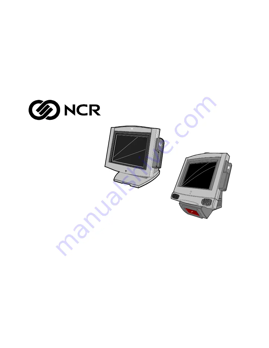
NCR 7401 Web Kiosk

Release 2.3

Hardware User's Guide

16436

NCR

B005-0000-1254

Issue D

Содержание 7401 Web Kiosk

Страница 1: ...NCR 7401 Web Kiosk Release 2 3 Hardware User s Guide 16436 NCR B005 0000 1254 Issue D...

Страница 2: ...res functions and operations described herein may not be marketed by NCR in all parts of the world In some instances photographs are of equipment prototypes Therefore before using this document consul...

Страница 3: ...supply cord is used as the main disconnect device Ensure that the socket outlet is located installed near the equipment and is easily accessible Attention Le cordon d alimentation est utilis comme int...

Страница 4: ...type recommand par le constructeur Mettre au r but les batteries usag es conform ment aux instructions du fabricant Peripheral Usage This terminal should only be used with peripheral devices that are...

Страница 5: ...Preparation Guide B005 0000 1255 NCR 7401 Web Kiosk Software User s Guide B005 0000 1258 NCR 7401 7454 Retail Terminal Parts Identification Manual B005 0000 1072 NCR 74017454 Retail Terminal Diagnost...

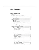
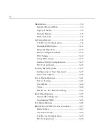
Страница 6: ...stem Configuration Diagram 1 8 Kit Configuration Diagram 1 9 Hardware Module Descriptions 1 10 Processor Board 1 10 Processor Chip Set 1 10 Video Subsystem 1 11 Ethernet 10 100Base T LAN Communication...

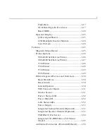
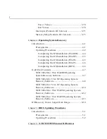
Страница 7: ...7158 Printer 1 28 7166 Printer 1 28 7194 Printer 1 29 7196 Printer 1 29 Other Integrated Devices and Indicators 1 30 Hard Disk Drive 1 30 Reset Switch 1 30 Internal Speaker 1 30 POS Connector Board 1...

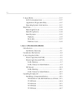
Страница 8: ...lation Introduction 2 1 Installation Summary 2 1 Installation Restrictions 2 2 Connecting the Cables 2 3 Fixed Angle Mount F504 2 3 Fixed Angle Mount F503 2 5 Cable Routing 2 7 Cable Connector Identif...

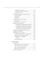
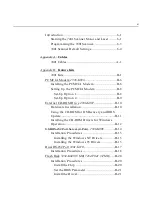
Страница 9: ...ing the OS Installation Win98 2 38 Completing the OS Installation Win95 2 39 Completing the OS Installation DOS 2 39 Setting Auto Logon WinNT Terminal 2 40 Installing a Serial Mouse 2 45 Calibrating t...

Страница 10: ...cured Setup Configurations 3 15 PCI Configuration 3 16 Security Menu Options 3 19 Set Supervisor User Password 3 19 Password on Boot 3 20 Power Menu Options 3 21 Power Savings 3 21 Fixed Disk 3 24 Vid...

Страница 11: ...r 3 41 System Monitors 3 47 Multiple ROM Menu 3 48 Advanced Chipset Control 3 50 ECC Config 3 52 Security Menu Options 3 56 Set Supervisor User Password 3 56 Diskette Access 3 57 Fixed Disk Boot Secto...

Страница 12: ...4 6 Completing the OS Installation DOS 4 6 Gold Disk Contents 4 7 NCR 7401 22xx 35xx Win2000 Operating System Recovery Software 4 7 NCR 7401 22xx 35xx NT Operating System Recovery Software 4 8 NCR 74...

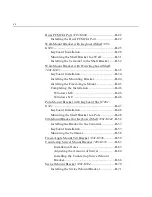
Страница 13: ...xternal CD ROM Drive 2336 K007 B 10 Hardware Installation B 10 Using the CD ROM for OS Recovery and BIOS Update B 11 Installing the CD ROM Drivers for Windows Operation B 12 USB RS 232 Port Server 4 P...

Страница 14: ...ing the Installation B 46 Windows ME B 46 Windows NT B 46 Pole Mount Bracket with Keyboard Shelf 7401 K541 B 47 Keyboard Installation B 48 Mounting the Shelf Bracket to a Pole B 48 Tilt Mount Bracket...

Страница 15: ...Core Module B 91 Connecting the Cables B 92 Self Service Printer 7401 K580 and 7401 K590 B 93 Mounting the Printers B 93 Wall Mount Printer only B 95 Pole Mount Printer only B 97 Wall Mount Printer a...

Страница 16: ...nter 7453 K641 B 147 Installation Procedures B 147 Usage Restrictions B 148 12 1 LCD No Cabinet Feature 7401 F752 and 7401 F753 B 149 Installation Guidelines B 149 Mounting Specification Illustrations...

Страница 17: ...document which was previously called the 7401 Web Kiosk Hardware Installation and Service Guide B005 0000 1254 and renamed it the 7401 Web Kiosk Hardware User s Guide B005 0000 1254 The hardware serv...

Страница 18: ...ion interference caused by unauthorized modification of this equipment or the substitution or attachment of connecting cables and equipment other than those specified by NCR The correction of interfer...

Страница 19: ...inet Laser Power The NCR 7401 Scanner is not intended for long term viewing of direct laser light However the unit is safe if used as intended This scanner meets the following laser LED power requirem...

Страница 20: ...atterson Boulevard Dayton OH 45459 USA declares that the equipment specified above conforms to the referenced EU Directives and Harmonized Standards EU Directive Harmonized Standard s 89 336 EEC EMC E...

Страница 21: ...act cabinet and can be tilt mounted or fixed angle mounted The major hardware features of the 7401 are a 12 1 or 15 flat panel display with touch screen input and LAN connectivity plus optional magnet...

Страница 22: ...llowing sections for additional information 1RWH The serial number is repeated on the non MSR side of the Core Module Fixed Angle Mount Label To view the label For non hinged mounts remove the Core Mo...

Страница 23: ...verview 1 3 Tilt Mount Label To view the label tilt the Core Module and remove the cable cover 7454 2212 M007 50 32758815 50 000077 Mfg Date 06 29 98 NCR 0 Class Model Serial Number Tracer Number Date...

Страница 24: ...PC Audio with an internal mono speaker SoundBlaster 16 compatible audio chipset Two USB type A ports PS 2 keyboard port External VGA display port This does not allow different information on each disp...

Страница 25: ...passive models 2 5 low or high capacity hard disk Integrated Motion Sensor capable of waking up the terminal from a low power state Integrated Power Supply Reset switch which can be used to recover fr...

Страница 26: ...rawer cable Printers 7158 Thermal Receipt Impact Printer 7194 Thermal Receipt Printer 7196 Thermal Receipt Printer Remote printer cables Signal extenders for remote printers 7401 K580 Self Service Pri...

Страница 27: ...communication to an NT server via standard protocols SLP terminal loading Local storage TCP IP networking and PXE loading Keylock for security X L R S Reset switch based security ISA and PCI Expansion...

Страница 28: ...nd Cash Drawer Y Cable 7194 PS 2KBD VGA USB Audio RS232 4 2 Optionally Powered Cash Dwr 2336 K007 Ethernet 2336 K008 2113 7196 7166 2010 Coin Dispenser SVideo 7158 7892 Processor Board Note 7194 and 7...

Страница 29: ...Chapter 1 Product Overview 1 9 Kit Configuration Diagram 7401 2xxx 7401 3xxx K542 K533 F501 K530 K525 K523 K580 F504 F511 F521 F101 F201 F502 F200 18318c 7401 w K580 K540 K543 K534 K535 K536 K033 K037...

Страница 30: ...bility Java Benchmark performance 1000 Caffeinemarks JIT compiled OS support to run Java Expansion capabilities for optional features and future requirements ISA PCI bus and USB The processor is one o...

Страница 31: ...creased tube life If appropriate software drivers are loaded full brightness is restored when touched motion detection Motion Sensor section or an application request i e to play promotional material...

Страница 32: ...d 100 or 10 100 hubs must be installed NCR strongly recommends the use of Category 5 for all new cabling even if the customer initially intends to run only 10Base T LED Indicators for Link Integrity v...

Страница 33: ...infrastructure and access points 802 11 does not govern this operation Mixing of RF suppliers on a site is not recommended until the RF suppliers have demonstrated interoperability The wireless networ...

Страница 34: ...erly set up in the BIOS The total power drawn by Ports 1 and or 3 must be within the limits of the capabilities of the power supply Refer to the following table for RS 232 pin out information The BIOS...

Страница 35: ...audio Wave table synthesis is not supported FM synthesis and MIDI are supported in the hardware but requires software driver support to function Higher quality integrated stereo speakers may be added...

Страница 36: ...iver for the appropriate OS When the system is operating in the dimmed display mode touch activity can restore full brightness if instructed by software to do so When system is in low power mode touch...

Страница 37: ...amounts of non volatile storage flash disks up to 72 MB are available from M Systems The system sees these flash disks as hard drives when the proper software support is provided Flash Disk Interface...

Страница 38: ...olenoid B Control Turns off solenoid output Activates solenoid output 6 Solenoid A Control Turns off solenoid output Activates solenoid output 5 Reserved Reserved Reserved 4 Reserved Reserved Reserved...

Страница 39: ...h BIOS Setup Graphics Subsystem The Pentium Processor Board is equipped with a C T 69000 65555 SVGA LCD CRT graphics controller with 2 MB of integrated synchronous graphics DRAM The 69000 65555 is a 3...

Страница 40: ...600x24bpp 16 M 85 Hz Colors Supported Resolution 256 Colors 8 Bit 65 000 Colors 16 Bit 16 7 M Colors 24 Bit 800x600 512 k 1 MB 2 MB Board BIOS The Processor Boards use a Phoenix BIOS which is stored i...

Страница 41: ...S EE000H EFFFFH 8 kB System BIOS Reserved during boot ED000H EDFFFH 4 kB Plug and Play ESCD Storage Area E0000H ECFFFH 52 kB System VGA BIOS Reserved during boot BIOS Upgrades Flash memory makes distr...

Страница 42: ...too In either case the energy saving Standby mode can be initiated by a keyboard hot key sequence or a time out period set by the user When in Stand by mode the Processor Board reduces power consumpt...

Страница 43: ...re can set a default value after reading the Panel ID Display contrast changes with temperature The DSTN panels contain temperature compensation circuitry that adjusts contrast automatically as the te...

Страница 44: ...the Inverter Board may have been compromised and the Inverter Board should be replaced If one or both Backlight tubes become disconnected or otherwise open circuited protection circuitry shuts down t...

Страница 45: ...tures Magnetic Stripe Reader A single 3 track analog MSR is available as a feature supporting ISO format cards When the MSR is not desired a filler piece for the MSR section is included to make the un...

Страница 46: ...nt thermal printer that provides unattended printing The printer is housed in a secure cabinet that does not allow customer access to the paper while it is printing It can print text graphics and bar...

Страница 47: ...ting The printer is housed in a secure cabinet that does not allow customer access to the paper while it is printing It can print text graphics and bar codes It prints on paper that is 80 mm When prin...

Страница 48: ...that you insert It receives its power from an external power supply can be connected through a USB or serial port and has a connector for cash drawers 17304 7166 Printer The 7166 Printer is an extrem...

Страница 49: ...receipt station It receives its power from an external power supply can be connected through a USB or serial port and has a connector for cash drawers 16437 7196 Printer The 7196 Printer is a high spe...

Страница 50: ...t easily accessible but can be operated without removing covers or using special tools 16454 Reset Switch DXWLRQ Except when testing software in a lab environment always disconnect the AC power cord R...

Страница 51: ...l hardware can detect movement near the terminal and enables software to prompt system operation from a low power state Application software may also be able to make use of motion detection when in th...

Страница 52: ...and BIOS are operating properly The LED is mounted behind the front bezel on the same board as the motion sensor Power OK LED The Power OK LED is located behind the Cable Cover between the Customer D...

Страница 53: ...display PS 2 keyboard PCMCIA daughter board and slots scanner through RS 232 port USB hard disk and the LCD all receive power through their respective Processor Board connectors Integrated Scanner Mo...

Страница 54: ...SB RS 232 Port Server The USB RS 232 Port Server is an intelligent stackable expansion module that connects to the terminal Universal Serial Bus USB port providing high speed RS 232 serial ports 7454...

Страница 55: ...CD ROM Drive Tilt Mount Model The Integrated CD ROM Drive is located behind a cover on the Back Panel To access the drive loosen the spring loaded CD Cover Screw and remove the CD Cover by sliding it...

Страница 56: ...o RS 232 Connector COM 3 and COM 4 Microphone optional The following is a brief description of each connector S Video This connector allows for a video connection to an S video monitor RS 232 Connecto...

Страница 57: ...et IEEE 802 2 Link Level Control LLC TCP IP Application Programmability The software associated with the terminal systems conform to the following standards OLE for Retail POS 1 2 JavaPOS for Retail 1...

Страница 58: ...OPOS based applications can be supported on terminals running Windows NT Windows NT 95 98 are the only supported operating systems Limited support is provided for DOS none for OS 2 or any version of U...

Страница 59: ...does not support the following features found in previous retail systems Platform ISA Cards Standard PCI Cards Multi port Serial Memory Dump Networks M 11 StarLAN 10base2 Ethernet Token Ring NetBEUI N...

Страница 60: ...ping packaging and visual checks made to verify the correct hardware configuration The system is then configured and any communication cables are connected Only after inspection should the power cord...

Страница 61: ...c electricity from your body before servicing the terminal If the power cord is replaced it must be replaced with the same type of cord with the protective shroud Do not route the power cord through o...

Страница 62: ...ated behind the Core Module The procedure for accessing the connectors is different for Fixed Angle Mounts and Tilt Mounts Fixed Angle Mount F504 1 Remove the screws that secure the Core Module to the...

Страница 63: ...ttom of the Core Module pull out the Core Module Support and rest the Core Module on the Core Module Support 17340 Core Module Core Module Support Metal Locking Tabs Keyboard Port 3 Route the cables a...

Страница 64: ...Chapter 2 Hardware Installation 2 5 Fixed Angle Mount F503 1 Remove the screw that secures the Core Module to the Fixed Angle Mount Remove Screws one on each side 16396 Core Module Pedestal Mount...

Страница 65: ...2 6 Chapter 2 Hardware Installation 2 Remove the Core Module from the Fixed Angle Mount 16397 3 Route the cables as described in the following section Cable Routing...

Страница 66: ...pped from the factory routed through the bottom exit hole in the Fixed Angle Mount To route the cables out the rear exit you must move the grommet from the bottom exit to the rear exit hole Since thes...

Страница 67: ...ion 2 Press the grommet along the bottom edge of the rear exit and cut it to length 16482 Measure and Cut 3 Install the remainder of the grommet to the other three sides of the opening 16483 Trim the...

Страница 68: ...LAN USB 2 COM 1 COM 2 Keyboard PS 2 Parallel Power Audio Out Cash Drawer Speaker S Video RS 232 COM 3 4 Microphone optional IRDA USB 1 1RWH COM1 and COM3 can be powered ports They are enabled in the...

Страница 69: ...ilt Mount cable connectors are located on the underside of the Core Module under a cable cover 1 Tilt the display to access the cable connectors Cable Cover Thumb Screw 15968 2 Loosen the thumbscrew t...

Страница 70: ...e base of the unit two thumb screws on bottom rear and use a tie wrap to secure the Ethernet cable to one of the provided molded cable tie holders on the base This should provide sufficient strain rel...

Страница 71: ...instructions for each of the peripherals 18010 CRT LAN USB 1 COM 1 COM 2 Keyboard PS 2 Parallel Power Audio Out Cash Drawer Speaker S Video RS 232 COM 3 4 IRDA Microphone optional USB 2 1RWH COM1 and...

Страница 72: ...llation 2 13 Installing Peripherals Installing a Transaction Printer 7401 K580 or 7401 K590 Self Service Printer For information about installing the K580 or K590 self service printer refer to the Fea...

Страница 73: ...r located on the underside of the printer Printer Connector RS232 Cash Drawer Power Connector 17333 2 Connect the other end of the printer cable to a USB port or one of the RS 232 ports non powered on...

Страница 74: ...printer located on the underside of the printer Printer Connector RS232 Cash Drawer Power Connector 17332 2 Connect the other end of the printer cable to one of the RS 232 ports non powered on the te...

Страница 75: ...Connector Power Connector Cash Drawer Connector 2 Connect the other end of the printer cable to a USB port or one of the RS 232 non powered ports on the terminal 3 Connect the Power Brick cable to the...

Страница 76: ...printer located on the underside of the printer Printer Connector RS232 Cash Drawer Power Connector 17331 2 Connect the other end of the printer cable to one of the RS 232 non powered ports on the te...

Страница 77: ...sh Drawer 1 Place the cash drawer in the desired location within cable length of the terminal 16269 2 Connect the cash drawer cable to the terminal cash drawer connector 15969c Cash Drawer 1RWH The Ca...

Страница 78: ...Y cable to the terminal cash drawer connector 16270 Dual Cash Drawer Y Cable 1416 C372 0006 1RWH The Y cable can optionally be connected to the printer Installing PC Cards PC cards wireless modem etc...

Страница 79: ...2 20 Chapter 2 Hardware Installation 1 Remove the screws that secure the Core Module to the Fixed Angle Mount Remove Screws one on each side 16396 Core Module Pedestal Mount...

Страница 80: ...Chapter 2 Hardware Installation 2 21 2 Remove the Core Module from the Fixed Angle Mount 16397...

Страница 81: ...Hardware Installation 3 Remove the Wireless Antenna Cover 18615 Wireless Antenna Cover Screws 2 Wireless Antenna Cover Screws 2 Tilt Mount Model Fixed Angle Mount Model 4 Insert the PC card wireless...

Страница 82: ...ount can be installed on a Pedestal or on the edge of a flat horizontal surface Wall Pole 16414 Pedestal Mount Wall Mount Pole Mount The sections that follow describe how to perform these installation...

Страница 83: ...to hang over the edge of the surface 2 The cables for the 7401 can be routed through an opening in the back of the Fixed Angle Mount or you can remove the plastic knockout in the bottom of the mount t...

Страница 84: ...use the K521 Wall Mount Bracket Kit 1 Secure the Wall Bracket to the wall with lag screws into the studs or with hardware of similar strength The recommended viewing height for the terminal is 1 2 m 4...

Страница 85: ...2 26 Chapter 2 Hardware Installation 2 Install the slots on back of the Fixed Angle Mount onto the locking tabs of the Wall Bracket 16416...

Страница 86: ...pole use the K520 Post Mount Bracket Kit same as K521 but includes strap kit 16392 1 2 m 48 in Recommended Height from Floor 1 Cut two metal straps to length pole circumference plus 2 inches 2 Loop o...

Страница 87: ...elow 18009 Wall Bracket Locking Tabs facing away from pole and pointing up Insert clamp into slot Route clamp through opening nearest to pole 1RWH There are two openings that the clamp can be routed t...

Страница 88: ...Chapter 2 Hardware Installation 2 29 4 Insert the metal strap through the opening on the opposite side of the Wall Bracket 16405 Route the strap through the slot...

Страница 89: ...30 Chapter 2 Hardware Installation 5 Wrap the metal strap around the pole and loop it through the other end of the clamp 16406 6 Snug the clamp and then crimp the metal strap with a pair of pliers 164...

Страница 90: ...Chapter 2 Hardware Installation 2 31 7 Using a 5 16 nut driver tighten the clamp DXWLRQ Do not over tighten the clamps 16407 8 Repeat the previous steps for the second clamp...

Страница 91: ...2 32 Chapter 2 Hardware Installation 9 Install the slots on back of the Fixed Angle Mount onto the locking tabs of the Wall Bracket 16392 1 2 m 48 in Recommended Height from Floor...

Страница 92: ...Chapter 2 Hardware Installation 2 33 10 For a pole mount installation route the cables through the Wall Bracket as shown below 16408...

Страница 93: ...34 Chapter 2 Hardware Installation Installing a Tilt Mount Terminal A Tilt Mount terminal can be installed on a flat horizontal surface or a flat vertical surface 16429 NCR Wall Mount Table Top Mount...

Страница 94: ...ith hardware of similar strength The recommended viewing height for the terminal is 1 2 m 48 from the floor 16400 Wall Plate Wall Mount Adapter Plate Release Lever 2 Install the Wall Mount Adapter Pla...

Страница 95: ...Wall Mounting a Core Module To flush mount the Core Module on a flat vertical surface use the F502 Flush Mount Bracket Kit 16683 Flush Mount w Power Supply Mounted on the Outside Wall Flush Mount w Po...

Страница 96: ...ting the power supply on the opposite side of the wall 16684 Flush Mounting Bracket Wall Plate Cable Routing Cable Routing through wall 2 Mount the Power Supply to the wall with screws 4 3 Route all c...

Страница 97: ...eboots press Next at the Windows Setup screen 2 Accept the Microsoft license agreement 3 Enter the User Name and Organization 4 Enter the Computer Name for the client 5 Enter the Administrator s Accou...

Страница 98: ...Win95 The system automatically reboots when the image recovery is complete and starts the software installation This installation also installs most of the additional software and drivers that are inc...

Страница 99: ...want to use to logon to the client s a Open the User Manager Select the Windows Start button select Programs Administrative Tools Common and then Select User Manager b Select the User menu and then se...

Страница 100: ...ter turn off the auto logon function e Select OK to close the Group Membership box f Select OK to create the account 2 Modify the Registry Select the Windows Start button and select Run 3 Enter regedi...

Страница 101: ...42 Chapter 2 Hardware Installation 5 Create a new string value to permit auto logon for the default user Select the Edit menu select New and then select String Value 6 Name the new entry AutoAdminLogo...

Страница 102: ...er the value 1 for auto logon 1RWH A value of 0 sets it to no auto logon 8 Select OK to set the value 9 Modify the DefaulUserName to contain the user ID that you want to automatically logon With the D...

Страница 103: ...ltPassword 13 Edit the string value With DefaultPassword selected select the Edit menu and then select Modify Enter the value of the password of the default user from Step 1 The example below uses pas...

Страница 104: ...x labeled Read Only and then select OK h Open the boot ini file with Notepad It should have the following entries operating systems multi 0 disk 0 rdisk 0 partition 1 WINNT Windows NT Workstation Vers...

Страница 105: ...ation Recalibrate whenever the terminal is moved to a new location Recalibrate the touch screen anytime the system has been disassembled for servicing The Touch Screen can be calibrated using MicroTou...

Страница 106: ...ing towards it and hold it until the statement Touch Enable is displayed over the finger icon 1RWH For best results press the screen near the circle and then slide your finger onto the circle without...

Страница 107: ...rol Panel Calibration Using Microcal DOS The calibration program looks at where your finger is when you lift it off the screen not where you touch it Therefore calibrate the screen as follows 1 Touch...

Страница 108: ...to be working normally then this message can be ignored There will be a check box labeled Do not show this message again Make sure this box is checked Calibration From the BIOS 1 Apply power to the t...

Страница 109: ...ce the Processor Board If this corrects the problem then the old glass is probably OK to reuse Out of Box Failures The RSG Atlanta Customer Satisfaction Hotline will replace out of box failed hard dis...

Страница 110: ...rs touch the screen three times This causes the system to bypass the BIOS Setup and go directly to the Touch Screen Calibration Setup With Pentium III Celeron terminals you will not see this prompt if...

Страница 111: ...tup can also be entered from the Boot Menu that is displayed when you press ESC during POST How to Select Menu Options The following keyboard controls are used to select the various menu options and t...

Страница 112: ...ess F9 The terminal will automatically load BIOS default CMOS values for boot up To reset all BIOS settings to their default settings go to the Exit menu press F9 select either Save Changes Exit or Sa...

Страница 113: ...030 however the hardware continues beyond 2030 To set the date and time perform the following steps 1 Move your cursor to the System Time option enter the desired value and press Tab or Enter to conti...

Страница 114: ...m Specific Help System Date 02 29 1997 Primary Master 2163MB Item Specific Help Type Auto Cylinders 4200 Heads 16 Sectors 63 Maximum Capacity 2168MB Multi Sector Transfers 16 Sectors LBA Mode Control...

Страница 115: ...Menu appears System Time 12 34 00 Item Specific Help System Date 02 29 1997 Memory Cache Item Specific Help Memory Cache Enabled Cache System BIOS area Enabled Cache Video BIOS area Disabled 2 Move th...

Страница 116: ...on 9 Move the cursor to the Exit Menu select Save Changes Exit or Save Changes and press Enter Cache Video 10 Move the cursor to the Cache Video BIOS area option 11 Press Enter and then select the des...

Страница 117: ...Board I O Device Configuration Move the cursor to the I O Device Configuration option and press Enter The options on this menu are used to configure peripherals System Time 12 34 00 Item Specific Hel...

Страница 118: ...nd then select the desired setting from the drop down menu Serial Port x This option is used to configure the serial ports A B 1 Move the cursor to the Serial port x option 2 Press Enter and then sele...

Страница 119: ...rop down menu Parallel Port This option is used to configure the parallel port 1 Move the cursor to the Parallel Port option 2 Press Enter and then select the desired setting from the drop down menu D...

Страница 120: ...down menu Floppy Disk Controller This option is used to configure the Floppy Disk Controller Since there is no floppy disk on the terminal this option is set to Disable Disk On Chip Address This optio...

Страница 121: ...to load unload specific ROMs the next time the system is started System Time 12 34 00 Item Specific Help System Date 02 29 1997 Multiple ROM Menu Item Specific Help On board Intel Lan 30 kB Enabled P...

Страница 122: ...or ROM usage information ROM Use On board Intel LAN This is the Boot ROM for the On board Intel Ethernet Lucent WaveLAN PXE Base These ROMs both parts required are for use with Lucent WaveLAN ROM 8021...

Страница 123: ...e This option is used to configure the parallel port 1 Move the cursor to the PS 2 Mouse option 2 Press Enter and then select the desired setting from the drop down menu Selecting Disabled prevents an...

Страница 124: ...O S Select Other if you are using UNIX Novell NetWare or other type of operating system 1RWH Only the Windows NT Operating System is supported Secured Setup Configurations 1 Move the cursor to the Se...

Страница 125: ...Configuration Item Specific Help ISA graphics device installed No PCI PNP ISA UMB Region Exclusion PCI PNP ISA IRQ Resource Exclusion ISA Graphics Device Installed 1 Move the cursor to the PCI Config...

Страница 126: ...lay the options System Time 12 34 00 Item Specific Help System Date 02 29 1997 PCI PNP ISA UMB Region Exclusion Item Specific Help C800 CBFF Available CC00 CFFF Available D000 D3FF Available D400 D7FF...

Страница 127: ...he options System Time 12 34 00 Item Specific Help System Date 02 29 1997 PCI PNP ISA IRQ Resource Exclusion Item Specific Help IRQ 3 Available IRQ 4 Available IRQ 5 Available IRQ 7 Reserved IRQ 9 Ava...

Страница 128: ...is not present To enter a password follow these steps 1RWH The User Password cannot be set until after the Supervisor Password is set 1 Move the cursor to the Set Supervisor Password or Set User Pass...

Страница 129: ...option enables disables the password entry on boot 1RWH User Password must also be set 1 Move the cursor to the Password on boot option and press Enter 2 Press Enter and then select the desired settin...

Страница 130: ...ng Disabled PCI Bus Monitoring Disabled Power Savings This option is used to select the power management mode Standby Timeout and Auto Suspend Timeout 1 Move the cursor to the Power Savings option 2 U...

Страница 131: ...s 1 Move the cursor to select the Standby Timeout option 2 Press Enter and then select the desired setting from the drop down menu 3 Move the cursor to select the Auto Suspend Timeout option 4 Press E...

Страница 132: ...Chapter 3 Setup 3 23 5 Move the cursor to the Exit Menu select Save Changes Exit or Save Changes and press Enter...

Страница 133: ...agement of the video during Standby and Suspend To set this option perform the following steps 1 Move the cursor to the Video option 2 Press Enter and then select the desired setting from the drop dow...

Страница 134: ...ect a device 3 Press to move it up the list or to move it down the list 4 Move the cursor to the Exit Menu select Save Changes Exit or Save Changes and press Enter 1RWH Pressing ESC during POST causes...

Страница 135: ...Exit after writing all changed option values to CMOS memory Exit Discarding Changes Exit without saving changed option values to CMOS memory Load Setup Defaults Load default value for all BIOS option...

Страница 136: ...nd the correct BIOS is automatically installed Main Values System Time variable System Date variable Legacy Diskette A 144 MV 1 25 MV 3 Legacy Diskette B Disabled IDE Primary Master Type Auto Cylinder...

Страница 137: ...area Enabled Cache Video BIOS area Disabled System Memory 640 kB Extended Memory 31744 kB Power Savings Disabled Standby Timeout Off Auto Suspend Timeout Off Fixed Disk Disabled Video Disabled IDE Dri...

Страница 138: ...ST Disabled Advanced Values I O Device Configuration Local Bus IDE adapter Primary Serial port A Auto Serial port B Auto Mode Normal Parallel port Auto Mode Bi directional Floppy disk controller Disab...

Страница 139: ...3 30 Chapter 3 Setup Large Disk Access Mode DOS Secured Setup Configurations No PCI Configuration ISA Graphics Device Installed No PCI PNP ISA UMB Region Exclusion Available all...

Страница 140: ...nterval Timer 1 Reserved Keyboard buffer full 2 Reserved Cascade interrupt 3 Serial Port 2 4 Serial Port 1 5 User available 6 Reserved Floppy 7 Parallel Port 1 8 Real Time Clock 9 NCR Motion Thermal i...

Страница 141: ...ription FECFF000 FECFF01B 27 LAN PXE ROM 100000 10000000 255 MB Extended memory F0000 FFFFF 64 kB System BIOS EE000 EFFFF 8 kB Main BIOS available as UMB ED000 EDFFF 4 kB ESCD plug and play configurat...

Страница 142: ...Date Year 2000 is supported The BIOS can only set the year up to 2030 however the hardware continues beyond 2030 To set the date and time perform the following steps 1 Move your cursor to the System...

Страница 143: ...press Enter and the following sub menu appears Primary Master 2163MB Item Specific Help Type Auto Cylinders 4200 Heads 16 Sectors 63 Maximum Capacity 2168MB Multi Sector Transfers 16 Sectors LBA Mode...

Страница 144: ...Configuration Data No Cache Memory PS 2 port Touchscreen USB Port 2 Primary I O Device Configuration System Monitors Multiple ROM Menu Large Disk Access Mode DOS Local Bus IDE Adapter Both Advanced C...

Страница 145: ...649k Write Back Cache Extended Memory area Disabled Cache A000 AFFF Disabled Cache B000 BFFF Disabled Cache C800 CBFF Disabled Cache CC00 CFFF Disabled Cache D000 D3FF Disabled Cache D400 D7FF Disabl...

Страница 146: ...Move the cursor to the Exit Menu select Save Changes Exit or Save Changes and press Enter Cache Video BIOS 1 Move the cursor to the Cache Video BIOS area option 2 Press Enter and then select the desir...

Страница 147: ...roller Disabled Serial port C Enabled Mode Normal Base I O Address 220 Interrupt IRQ 11 Scanner Power Auto Serial port D Enabled Base I O Address 228 Serial Port x This option configures the serial po...

Страница 148: ...pin on COM 1 when on 12 V is present on pin 9 1 Move the cursor to the Scanner Power option 2 Press Enter and then select the desired setting from the drop down menu Auto detect scanner device and tur...

Страница 149: ...the drop down menu Disabled no configuration Enabled user configuration Auto BIOS or OS chooses configuration OS Controlled displayed when controlled by OS Mode This option sets the mode for the paral...

Страница 150: ...setting from the drop down menu Floppy Disk Controller This option configures the Floppy Disk Controller Since there is no floppy disk on the terminal this option is set to Disable Mode Port C This o...

Страница 151: ...se I O address option 2 Press Enter and then select the desired setting from the drop down menu Interrupt Port C This option sets the interrupt for serial port C 1 Move the cursor to the Interrupt opt...

Страница 152: ...pin on COM 1 when on 12 V is present on pin 9 1 Move the cursor to the Scanner Power option 2 Press Enter and then select the desired setting from the drop down menu Auto detect scanner device and tur...

Страница 153: ...the desired setting from the drop down menu Interrupt Port D This option sets the interrupt for serial port D 1 Move the cursor to the Interrupt option 2 Press Enter and then select the desired setti...

Страница 154: ...Chapter 3 Setup 3 45 2 Press Enter and then select the desired setting from the drop down menu Other RS 232...

Страница 155: ...range used by the Disk On Chip 1 Move the cursor to the Disk On Chip option 2 Press Enter and then select the desired setting from the drop down menu MSR Address This option selects the memory address...

Страница 156: ...er 1 Move the cursor to the MSR Interrupt option 2 Press Enter and then select the desired setting from the drop down menu System Monitors Move the cursor to the System Monitors option and press Enter...

Страница 157: ...nly enable the required ROMs Refer to the following table for ROM usage information ROM Use On board Intel LAN Intel Ethernet hardware specific portion of the Ethernet Boot ROM Requires the On board I...

Страница 158: ...ther if you are using UNIX Novell NetWare or other type of operating system 1RWH Only the Windows NT Operating System is supported Local Bus IDE Adapter This option is used to enable disable the integ...

Страница 159: ...ess Enter and the following sub menu appears Advanced Chipset Control Item Specific Help Graphics Aperture 64 MB Enable memory gap Disabled ECC Config Disabled SERR signal condition Multiple bi Defaul...

Страница 160: ...rop down menu Enable Memory Gap This option frees address space for use with an option card 1 Move the cursor to the Enable Memory Gap option 2 Press Enter and then select the desired setting from the...

Страница 161: ...enu Disabled all memory does not support ECC x72 EC checking only ECC checking and correction ECC Scrub checking correction with scrubbing SERR Signal Condition This option selects the ECC error condi...

Страница 162: ...stalled AGP card for the boot display device PCI PNP ISA IRQ Resource Exclusion This option reserves specific IRQs for use by legacy device 1 Move the cursor to the PCI PNP ISA IRQ Resource Exclusion...

Страница 163: ...time diagnostic screen is disabled you will see the logo instead of the post results If an error occurs the terminal will beep and may wait for user input before booting but not automatically display...

Страница 164: ...QuickBoot Mode option 2 Press Enter and then select the desired setting from the drop down menu Continuous POST This option is enables POST to repeat in a loop until canceled 1 Move the cursor to the...

Страница 165: ...ar indicates that a password is not present To enter a password follow these steps 1RWH The User Password cannot be set until after the Supervisor Password is set 5 Move the cursor to the Set Supervis...

Страница 166: ...ter 2 Press Enter and then select the desired setting from the drop down menu Fixed Disk Boot Sector When write protect is selected the boot sector on the hard disk is write protected to protect again...

Страница 167: ...option enables disables the password entry on boot 1RWH User Password must also be set 3 Move the cursor to the Password on boot option and press Enter 4 Press Enter and then select the desired settin...

Страница 168: ...his option is used to select the power management mode Standby Timeout and Auto Suspend Timeout 1 Move the cursor to the Power Savings option 2 Press Enter and then select the desired setting from the...

Страница 169: ...op down menu 3 Move the cursor to select the Auto Suspend Timeout option 4 Press Enter and then select the desired setting from the drop down menu 5 Move the cursor to the Exit Menu select Save Change...

Страница 170: ...ive x Monitoring option 2 Press Enter and then select the desired setting from the drop down menu PCI Bus Monitoring This option enables disables activity on the PCI bus to keep the system awake 1 Mov...

Страница 171: ...ove the cursor to the Boot Sequence option on the Main Menu 2 Move the cursor to select a device 3 Press to move it up the list or to move it down the list 4 Move the cursor to the Exit Menu select Sa...

Страница 172: ...ed option values to CMOS memory Exit Discarding Changes Exit without saving changed option values to CMOS memory Load Setup Defaults Load default value for all BIOS options Does not exit Discard Chang...

Страница 173: ...Main Values 1RWH An asterisk indicates a variable value based on system specification etc System Time System Date Legacy Diskette A Disabled Legacy Diskette B Disabled Primary Master 2168 MB Type Auto...

Страница 174: ...ard Ultra DMA Mode Disabled Secondary Slave None Type Auto Multi Sector Transfers Disabled LBA Mode Control Disabled 32 Bit I O Disabled Transfer Mode Standard Ultra DMA Mode Disabled System Memory 64...

Страница 175: ...ache D400 D7FF Disabled Cache D800 DBFF Disabled Cache DC00 DFFF Disabled Cache E000 E3FF Write Protect Cache E400 E7FF Write Protect Cache E400 E7FF Write Protect Cache EC00 EFFF Write Protect PS 2 P...

Страница 176: ...Q 11 Mode RS 232 Disk On Chip Address CE00 CFFF MSR Address CC00 CDFF MSR Interrupt 15 System Monitors 12 V Status 2 5 V Status 5 V Status CPU Temperature System Temperature Vcc Status Vcore Status Vi...

Страница 177: ...led Selectable ROM 13 Disabled Selectable ROM 14 Disabled Selectable ROM 15 Disabled Selectable ROM 16 Disabled Large Disk Access Mode DOS Local Bus IDE Adapter Primary Advanced Chipset Control Graphi...

Страница 178: ...FFF Available PCI PNP ISA IRQ Resource Exclusion IRQ 3 Available IRQ 4 Available IRQ 5 Available IRQ 7 Available IRQ 9 Available IRQ 10 Available IRQ 11 Available Boot Time Diagnostic Screen Disabled...

Страница 179: ...on Boot Disabled Power Values Power Savings Disabled Standby Timeout Off Auto Suspend Timeout Off IDE Drive 0 Monitoring Disabled IDE Drive 1 Monitoring Disabled IDE Drive 2 Monitoring Disabled IDE D...

Страница 180: ...that follow the table IRQ System Resource NMI I O channel check 0 Reserved interval timer 1 Reserved keyboard buffer full 2 Reserved cascade interrupt 3 Serial port 2 4 Serial port 1 5 Free 6 Floppy...

Страница 181: ...onfigure it to use IRQ 5 2 Disable the Floppy Drive if not used then enable COM3 and configure it to use IRQ 6 3 Disable the Parallel Port if not used then enable COM3 and configure it to use IRQ 7 1R...

Страница 182: ...hex Size Description FECFF000 FECFF01B 27 LAN PXE ROM 100000 10000000 255 MB Extended memory F0000 FFFFF 64 kB System BIOS EE000 EFFFF 8 kB Main BIOS available as UMB ED000 EDFFF 4 kB ESCD plug and pl...

Страница 183: ...3 74 Chapter 3 Setup...

Страница 184: ...ated 7401 F058 F059 External 2336 K007 The terminal BIOS must be 1 02 00 00 or greater Keyboard DXWLRQ When performing an OS recovery from a larger source image larger disk to a smaller destination di...

Страница 185: ...onnect the external CD ROM 2336 K007 drive to the parallel port on the terminal 2 Connect the opposite end of the CD ROM cable end with the power connector pigtail to the CD ROM drive parallel connect...

Страница 186: ...Advanced menu select Multiple ROM Menu 8 Set the Parallel CD ROM Boot to Enabled 9 Exit Setup and Save Changes As the terminal reboots you should see a message during boot indicating that the CD ROM...

Страница 187: ...isk recovery from the CD It displays a progress bar and gives you an estimate how long the process should take When the recovery process is completed the client hard disk is restored to its preinstall...

Страница 188: ...he Microsoft license agreement 3 Enter the User Name and Organization 4 Enter the Computer Name for the client 5 Enter the Administrator s Account Password optional 6 When prompted press Finish to reb...

Страница 189: ...ation Win95 The system automatically reboots when the image recovery is complete and starts the software installation This installation also installs most of the additional software and drivers that a...

Страница 190: ...sion Audio driver installed version 5 12 01 3041 Intel R 82559 Fast Ethernet LAN driver installed version 5 00 67 0000 MicroTouch driver installed version 5 61 NCRSYSM driver installed version 2 01 01...

Страница 191: ...installed SoundFusion Audio driver installed Intel R 82559 Fast Ethernet LAN driver installed Intel PIIX Bus Master IDE drivers installed NCRSYSM driver installed Windows Installer installed M Systems...

Страница 192: ...A Preinstall the Product ID Number PID Places the Gold Drive Part Number Date Created LPIN and Version in Registry under HKey Local_Machine Software NCR Gold Drive Removes the following key from the r...

Страница 193: ...ideo driver installed CrystalWare Audio driver installed Intel EtherExpress software installed Intel PIIX Bus Master IDE drivers installed M Systems DiskOnChip 2000 driver not installed available Back...

Страница 194: ...e Part Number Date Created LPIN and Version in Registry under HKey Local_Machine Software NCR Gold Drive Windows Installer Version 1 1 installed Removes the following key from the registry as a curren...

Страница 195: ...hernet LAN driver installed version 5 00 67 0000 NCRSYSM driver installed version 2 01 01 003 Windows Installer Version 1 1 installed M Systems DiskOnChip 2000 driver available version 4 2 Backpack CD...

Страница 196: ...se Port software installed Chips Technologies 69000 Video driver installed Crystal Audio driver installed Intel 8255x based PCI Ethernet Adapter installed Intel PIIX Bus Master IDE drivers installed B...

Страница 197: ...the DOS screen prompts After each entry you are asked to confirm your input You can use 1 or y for Yes 2 or n for No 3 Enter No at the Disk verification question 4 Select which type of recovery you wa...

Страница 198: ...ze of the second partition O S Second Partition Format Second Partition Size NT NTFS Fill the remaining drive space Win2000 NTFS Fill the remaining drive space Win98 FAT32 Fill the remaining drive spa...

Страница 199: ...ser s Guide for information about that procedure Prerequisites The following are required on the 7401 in order to perform a BIOS update using a CD Bootable CD ROM drive Integrated 7401 F058 F059 Exter...

Страница 200: ...K007 drive to the parallel port on the terminal 2 Connect the opposite end of the CD ROM cable end with the power connector pigtail to the CD ROM drive parallel connector 18250 Parallel Connector Para...

Страница 201: ...OS 10 Follow the screen prompts on the client to update the BIOS You can select two methods to run the update program Automatic BIOS Update update process runs unattended Note You will see a prompt fo...

Страница 202: ...any key to reboot 14 Enter Setup when the terminal reboots and load the Setup Defaults Exit Menu 15 From the Advanced menu select Reset Configuration Data and then use the space bar to change the sel...

Страница 203: ...integrating the 7401 Scanner should obtain a copy of the following documents NCR 7890 Presentation Scanner User s Guide BD20 0901 A NCR Scanner Scale Interface Programmer s Guide BD20 1074 A Both of t...

Страница 204: ...period expires if the NCR OPOS scanner driver does not get another motion event the motor and laser are turned off If a motion event is received during the Active Time period the motor and laser will...

Страница 205: ...sign of these procedures should be carefully considered to limit customer frustration Programming the 7401 Scanner The 7401 Scanner cannot be programmed using the programming cards but as with the 789...

Страница 206: ...or the 7401 Scanner that are different from the defaults of the 7890 Hex Command ASCII Command Command Description Comments 31h 30h 35h 1 0 5 Select RS 232 protocol The 7401 Scanner can only be used o...

Страница 207: ...K rectangular 1416 C411 0030 006 1012224 Power international 1416 C419 0030 250 0023191 Power 120 V twist lock 1416 C041 0030 497 0008623 Ethernet 10 100BaseT 1416 C266 0152 497 0409379 7193 RS 232 50...

Страница 208: ...A 2 Appendix A Cables Corporate ID Part Number Description 1416 C464 0006 497 0413011 CD ROM 1416 C472 0006 497 0411000 Parallel interface...

Страница 209: ...label peeler 2337 K014 V001 497 0417709 Bravo 4 label printer UK cord without label peeler 2337 K015 V001 497 0417710 Bravo 4 label printer UK cord with label peeler 2336 K001 V001 497 0411988 Ethern...

Страница 210: ...ed angle to tilt mount conversion 7401 K503 V001 497 0412158 Fixed angle mount 7401 K520 V001 497 0411710 Pole mount bracket fixed angle mount 7401 K521 V001 497 0411711 Wall mount bracket fixed angle...

Страница 211: ...401 K901 V002 497 0417666 WIN BOM SCER 584 7401 K903 V001 497 0417822 Integrated CD ROM 7454 K040 V001 497 0411474 8 MB flash disk 7454 K101 V002 497 0412005 MSR 3 track ISO 7454 K102 V001 497 0412299...

Страница 212: ...ball 2756 K121 V001 497 0409421 Domestic power supply 2756 K122 V001 497 0409434 Y cable adapter mouse keypad 2756 K124 V001 497 0409422 International power supply 5945 K010 V002 497 0414162 Cable 4 M...

Страница 213: ...K280 V001 497 0408653 Slip table 7158 K301 V001 497 0411975 Power supply 55 W 7453 K002 V001 497 0407633 Modular cash drawer 2260 7453 K007 V001 497 0414767 Till with lid and lock 7452 K183 V001 497 0...

Страница 214: ...integrated unit This kit requires the presence of the Dual PCMCIA Port 7401 K060 Installing the PCMCIA Modem 1 Remove the Back Panel from the Core Module as described in the 7401 Web Kiosk Hardware S...

Страница 215: ...CIA Modem Cable Route the cable between the cabinet and sheet metal 4 Connect the Modem Cable to the PCMCIA Modem 5 Route the cable between the cabinet and sheet metal as shown above 6 Install the Ant...

Страница 216: ...Chip and Parallel Port Onboard LAN boot is the only option disabled Bios Option Setting Default Y N Serial Port A 3F8 IRQ4 Y Serial Port B 2F8 IRQ3 Y Parallel Port 378 IRQ 7 Y Floppy Disk Controller E...

Страница 217: ...ption Setting Default Y N Serial Port A 3F8 IRQ4 Y Serial Port B 2F8 IRQ3 Y Parallel Port 378 IRQ 7 Y Floppy Disk Controller Enabled Y Serial Port C Disabled N Serial Port D Disabled N Disk On Chip Di...

Страница 218: ...andard parallel interface and functions similar to a regular CD ROM Hardware Installation 1 Connect the CD ROM drive to the parallel port on the terminal disconnect the Customer Display if applicable...

Страница 219: ...press F2 to enter the BIOS Setup Utility 3 Select the Advanced Menu 4 Select the I O Device Configuration 5 Arrow down to the Parallel Port Mode 6 Use the space bar to select Bi directional Mode 7 Pre...

Страница 220: ...e CD ROM drive with Windows you must install the drivers manually The drivers are located on the terminal hard disk 1 Select Start Run Then type in the path to the BACKPACK setup program The program i...

Страница 221: ...Appendix B Feature Kits B 13 3 Select Install or Update BACKPACK Driver 4 Select Finish to restart the computer...

Страница 222: ...B 14 Appendix B Feature Kits USB RS 232 Port Server 4 Port 2336 K008 This device provides four additional RS 232 ports via the terminal USB port 16943 7454 7401 USB Port RS 232 Ports 16944...

Страница 223: ...the Start Menu select Run 3 Type a setup and then click OK 4 Click Next at the Edgeport Drivers Install screen 5 Read the Inside Out Networks Edgeport Software License If you agree click Yes 6 Read t...

Страница 224: ...n 6 Type a in the Copy File From field and then click OK Files will be copied from the disk to your system The Update Device Driver Wizard will appear a second time in order to install support for Win...

Страница 225: ...fer to the following table for RS 232 pin out information RS 232 DB 9 Male Connector Pin Out Pin Port A Port B 1 DCD DCD 2 RXD RXD 3 TXD TXD 4 DTR DTR 5 GND GND 6 DSR DSR 7 RTS RTS 8 CTS CTS 9 RI or 1...

Страница 226: ...two screws The following illustration shows the Connector Row Bracket with the the Interface Cable Connector Com 3 and 4 installed 18010 CRT LAN USB 1 COM 1 COM 2 Keyboard PS 2 Parallel Power Audio O...

Страница 227: ...rs J23 and J24 on the Motherboard 19104 Connect to J24 Connect to J23 Install in Connector Row Bracket 3 Use the screws provided to install the connector on the Connector Row Bracket 4 Complete the in...

Страница 228: ...rd IDE interface and functions similar to a regular hard disk The device is located on the Processor Board Installation Procedures Install the Chip 1 Install the Flash Disk on the Processor Board in t...

Страница 229: ...3 Select the Advanced menu 4 Select I O Device Configuration 5 Verify that Disk On Chip Address is set to CE00 CFFF Install the Driver 1 In Windows Explorer switch to the following folder c install d...

Страница 230: ...port for two PCMCIA devices on the terminal 1RWH Each PCMCIA device is a separate kit Installing the Dual PCMCIA Port 1 Remove the Back Panel from the Core Module 2 Remove the Filler Plate from the Ca...

Страница 231: ...16871 PCMCIA Assembly PCMCIA Bracket PCMCIA Connector a Connect the PCMCIA Assembly card to the Processor Board b Secure the assembly with the hex screw c Install the PCMCIA Bracket The bracket fits u...

Страница 232: ...B 24 Appendix B Feature Kits 5 Install the Antenna Cover and secure it with screws 2 16874 Wireless Antenna Cover...

Страница 233: ...Appendix B Feature Kits B 25 Wall Mount Bracket with Keyboard Shelf 7401 K540 17012 1RWH K540 does not include a keyboard To order a keyboard use part number 7102 0911 0000...

Страница 234: ...Feature Kits Keyboard Installation 1 Remove the 4 8 32 screws that secure the bottom plate to the Keyboard Shelf 17364 4 Screws 2 Remove the shelf top from the slide 17365 3 Insert the Keyboard into t...

Страница 235: ...Appendix B Feature Kits B 27 17366 4 Using a Phillips Head screwdriver install the two locking brackets 17367 Locking Bracket...

Страница 236: ...B 28 Appendix B Feature Kits 5 Route the keyboard cable through the shelf top 17373 6 Re install the shelf top in the slide 17372...

Страница 237: ...Appendix B Feature Kits B 29 7 Route the keyboard cable through the Keyboard Shelf Install Strain Relief Bushings and Cable Tie as illustrated 17368 Cable Tie Strain Relief...

Страница 238: ...B 30 Appendix B Feature Kits 8 Route the cable as shown Secure it with the Cable Tie Mount 1RWH Use alcohol to clean the area before mounting the Cable Tie Mount 17369 Strain Relief...

Страница 239: ...a Wall Secure the Wall Bracket to the wall with lag screws into the studs or with hardware of similar strength The recommended viewing height for the terminal is 1 2 m 48 from the floor 17351 Wall Bra...

Страница 240: ...the Terminal to the Shelf Bracket 1 Install the terminal to the Wall Bracket The back of the Fixed Angle Mount has slots that mate to locking tabs on the Keyboard Shelf Mounting Plate 2 Secure the ter...

Страница 241: ...elf 7401 K543 18501 1RWH K543 does not include a Wide Keyboard with Trackball To order a Wide Keyboard with Trackball use part number 2336 K020 The Wide Keyboard with Trackball requires the use of a S...

Страница 242: ...yboard Installation 1 At the rear of the Mounting Bracket release the Cable Chain from the Cable Chain Bracket by pushing down and out on the last link in the Cable Chain Push Down Pull Out 18522 1 2...

Страница 243: ...Appendix B Feature Kits B 35 2 Remove the screws that secure the Keyboard Shelf to the Bottom Plate 17364 4 Screws 3 Remove the Keyboard Shelf from the Bottom Plate 17365...

Страница 244: ...ature Kits 4 On the bottom of the Keyboard Shelf release the Cable Chain from the Cable Chain Bracket by lifting up and out on the last link in the Cable Chain 18523 Cable Chain Cable Chain Bracket 1...

Страница 245: ...Appendix B Feature Kits B 37 5 Insert the Keyboard into the Keyboard Shelf 18524 6 Using a nut driver install the two Keyboard Locking Brackets 18525 Locking Bracket...

Страница 246: ...B 38 Appendix B Feature Kits 7 Route the Keyboard Cable through the channel in the Keyboard Shelf and then install a Strain Relief Bushing 18526 Strain Relief Bushing...

Страница 247: ...able through the Cable Chain Bracket and then with the split side of the Cable Chain in the same plane as the Cable Chain Bracket Screws snap the Cable Chain onto the Cable Chain Bracket 18527 Cable C...

Страница 248: ...B 40 Appendix B Feature Kits 9 Uncoil the Keyboard Cable as much as necessary and push it through the split side of the Cable Chain 18528 Push Cable Into Chain...

Страница 249: ...Appendix B Feature Kits B 41 10 Slide the Keyboard Shelf onto the Bottom Plate and install the four screws 17372...

Страница 250: ...B 42 Appendix B Feature Kits 11 Route the Keyboard Cable through the Mounting Bracket and then snap the Cable Chain onto the Cable Chain Bracket 18529 Cable Chain Bracket Cable Chain...

Страница 251: ...Appendix B Feature Kits B 43 12 Install a Strain Relief Bushing through the Mounting Bracket 18530 Strain Relief Bushing...

Страница 252: ...ng Bracket Secure the Mounting Bracket to a wall with lag screws or with hardware of similar strength The recommended viewing height for the terminal is 1 2 m 48 from the floor 17351 Wall Bracket Lag...

Страница 253: ...ture Kits B 45 Installing the Fixed Angle Mount 1 Mate the slots in the back of the Fixed Angle Mount onto the locking tabs on the Mounting Bracket 2 Secure the Fixed Angle Mount with the two supplied...

Страница 254: ...will not work When a Serial Converter and Wide Keyboard with Trackball are installed on Windows 95 and Windows 98 systems the keyboard and trackball are automatically detected and become operational W...

Страница 255: ...7401 K541 The 7401 K540 and 7401 K541 kits are identical except that K541 contains mounting straps for mounting the unit to a pole 1RWH K541 does not include a keyboard To order a keyboard use part nu...

Страница 256: ...efer to the Keyboard Installation in the Wall Mount Bracket with Keyboard Shelf 7401 K540 section Mounting the Shelf Bracket to a Pole 1 Cut the metal strap to two equal lengths pole circumference plu...

Страница 257: ...Insert Clamp into slot Locking Tabs facing away from pole and pointing up Route clamp opening that is nearest pole Wall Bracket 1RWH There are two openings that the clamp can be routed through Use th...

Страница 258: ...B 50 Appendix B Feature Kits 4 Insert the metal strap through the opening on the opposite side of the Wall Bracket 17355 Route the strap through the slot...

Страница 259: ...Appendix B Feature Kits B 51 5 Wrap the metal strap around the pole and loop it through the other end of the clamp 17356...

Страница 260: ...B 52 Appendix B Feature Kits 6 Snug the clamp and then crimp the metal strap with a pair of pliers 17357...

Страница 261: ...Appendix B Feature Kits B 53 7 Using a 5 16 nut driver tighten the clamp DXWLRQ Do not over tighten the clamps 17358 8 Repeat the previous steps for the second clamp...

Страница 262: ...ppendix B Feature Kits 9 Install the terminal to the Mounting Plate The Fixed Angle Mount has slots that mate to locking tabs on the Mounting Plate 10 Secure the terminal with the two supplied screws...

Страница 263: ...Appendix B Feature Kits B 55 11 Route the cables in the Wall Bracket as shown below 17359...

Страница 264: ...01 K542 The Tilt Mount Bracket Adapter is used to mount a terminal that is configured with a tilt mount to a Keyboard Shelf This kit only includes the bracket You also need either 7401 K540 or 7401 K5...

Страница 265: ...er Plate to the tilt mount as illustrated below using the 4 8 32 plate screws 17361 Wall Mount Adapter Plate 4 Plate Screws Keyboard Installation The keyboard is mounted exactly as the 7401 K540 Refer...

Страница 266: ...B 58 Appendix B Feature Kits Mounting the Terminal 1 Align the mounting tabs and lower Tilt Mount Bracket on to the Keyboard Shelf 17362...

Страница 267: ...cket K534 or Countertop Swivel Mount Bracket K535 This section describes how to install a 7401 Fixed Angle Mount on the Fixed Angle Mount Tilt Bracket After installing a 7401 Fixed Angle Mount on the...

Страница 268: ...sure that all cables are exiting out the back of the Fixed Angle Mount 3 Guide all cables exiting out the back of the Fixed Angle Mount through the hole in the back if the Fixed Angle Mount Tilt Brac...

Страница 269: ...Appendix B Feature Kits B 61 4 With the 7401 s LCD face down on a flat surface slide the Fixed Angle Mount Tilt Bracket onto the Fixed Angle Mount 19067...

Страница 270: ...uide the cables through the hole in the bottom of the Fixed Angle Mount Tilt Bracket This completes the installation Do not install the Rear Cover on the back of the Fixed Angle Mount Tilt Bracket at...

Страница 271: ...be installed on Countertop Swivel Mount Bracket K535 The installation procedures for the three devices listed above are almost identical so the following sections describe how a 7401 Fixed Angle Mount...

Страница 272: ...ertop Swivel Mount Bracket 19059 Mounting Plate Release Lever Mounting Plate Screws Base Plate Swivel Base Adjusting the Amount of Swivel The Countertop Swivel Mount Bracket is shipped with the Mounti...

Страница 273: ...ase Plate not visible in illustration below slide the Swivel Base in the direction shown and lift it off the Base Plate 19061 Mounting Lever Screws Swivel Base 3 On the underside of the Swivel Base re...

Страница 274: ...a Countertop Swivel Mount Bracket 1 If the Swivel Base is not removed from the Base Plate remove it as detailed previously 2 If the amount of swivel is to be adjusted adjust it as detailed previously...

Страница 275: ...5 With the 7401 s LCD face down on a flat surface guide the cables through the hole in the Countertop Swivel Mount Bracket s Mounting Plate 19068 6 Slide the Countertop Swivel Mount Bracket onto the F...

Страница 276: ...Fixed Angle Mount Tilt Bracket to the Countertop Swivel Mount Bracket 19070 Screws Screws Screws Rear Cover 8 Using the four screws provided with the Fixed Angle Mount Tilt Bracket screw the Rear Cove...

Страница 277: ...lete the installation by rotating the assembly into an upright position and connecting the cables If the Countertop Swivel Mount Bracket will be secured to the countertop do not install the Base Plate...

Страница 278: ...the device installed on the swivel to rotate up to 340 degrees The sections that follow describe how to install the Swivel Mount Bracket on the checkstand Fixed Angle Mount on the Swivel Mount Bracke...

Страница 279: ...1 Installing the Swivel Mount Bracket 1 In the desired location drill an 88 9 mm 3 5 hole in the top of the checkstand for the Swivel Mount Bracket 7 mm 277 in 18465 88 9 mm 3 5 in 2 Place the Swivel...

Страница 280: ...e swivel cannot rotate and the display cannot be viewed directly The center of the Dead Zone is always 90 degrees from the tab in the flange Keep this in mind when planning the installation and markin...

Страница 281: ...Appendix B Feature Kits B 73 6 Use the Retaining Ring and the four Mounting Screws to secure the Swivel Mount Bracket to the checkstand 18498 Mounting Screws 4 Retaining Ring Checkstand...

Страница 282: ...ing a Fixed Angle Mount on the Swivel Mount Bracket Remove Core Module from Fixed Angle Mount 1 Remove the screws 2 that secure the Core Module to the Fixed Angle Mount 17119 Core Module Fixed Angle M...

Страница 283: ...Locking Tabs 3 Disconnect the AC Power Cable from the 7401 Power Supply located in the Fixed Angle Mount 4 Slide the Metal Locking Tabs forward to the Unlock position as shown in the previous illustra...

Страница 284: ...ppendix B Feature Kits 6 Remove the Core Module 17345 7 Remove the Swivel Mount Bracket and drill four 7 mm 277 holes in the marked locations 8 Place the Swivel Mount Bracket into the hole in the chec...

Страница 285: ...1 Align the slots in the bottom of the Fixed Angle Mount with the Locking Tabs on the Swivel Mount Bracket Lock the Fixed Angle Mount in place by sliding it toward the rear of the Swivel Mount Bracke...

Страница 286: ...unt Bracket Install Cover 1 Insert the two tabs on the Cover into the two lower slots on the back of the Fixed Angle Mount 17744 Cover 2 From inside the Fixed Angle Mount use the two screws with washe...

Страница 287: ...sembly can be installed on the Swivel Mount Bracket 1 Make sure the cables exiting out the back of the Fixed Angle Mount Tilt Bracket are routed through the hole in bottom of the Fixed Angle Mount Til...

Страница 288: ...xed Angle Mount Tilt Bracket to the Swivel Mount Bracket 5 Using the four screws provided with the Fixed Angle Mount Tilt Bracket screw the Rear Cover onto the Fixed Angle Mount Tilt Bracket 6 Complet...

Страница 289: ...egrated scanner cannot be used with a 7401 Tilt Mount 19099 NCR Tilt Mount Fixed Angle Mount Removing the Core Module The Core Module is attached to the Fixed Angle Mount one of two ways With F503 the...

Страница 290: ...B 82 Appendix B Feature Kits Removing the Core Module F503 1 Remove the screws that secure the Core Module to the Fixed Angle Mount Remove Screws one on each side 16396 Core Module Fixed Angle Mount...

Страница 291: ...Q Prevent damage to the Power Connector by pressing the latching tab in the bottom center of the connector when removing it from the Processor Board If the Power Connector is cable tied to the frame c...

Страница 292: ...B 84 Appendix B Feature Kits Removing the Core Module F504 1 Remove the screws that secure the Core Module to the Fixed Angle Mount 17339 Core Module Fixed Angle Mount Remove Screws One on each side...

Страница 293: ...t Metal Locking Tabs Keyboard Port 3 Note where the cables are connected and then disconnect them from the Core Module DXWLRQ Prevent damage to the Power Connector by pressing the latching tab in the...

Страница 294: ...B 86 Appendix B Feature Kits 5 Push in the Core Module Support and lower the Core Module 6 Remove the Core Module 17345...

Страница 295: ...ch the LCD 2 Remove the two screws that secure the Hinge and remove the Hinge 3 Replace the two screws that held the Hinge 4 Loosen the two screws on the bottom of the Rear Cover 5 Slide the Pivot Ass...

Страница 296: ...pendix B Feature Kits Removing the Power Supply from the Fixed Angle Mount 1 Remove the two screws that secure the Power Supply to the Fixed Angle Mount Power Supply Screws 2 16434 2 Remove the Power...

Страница 297: ...adjustable plastic strap through the loop in the Base Adjustable Plastic Strap 19184 2 Slide the tabs on the Power Supply into the slots in the Base 15977 3 Use the two hex screws to secure the Power...

Страница 298: ...B 90 Appendix B Feature Kits 5 Install the Power Supply Cover and then use the two Thumb Screws to secure the Power Supply Cover 19102 Thumb Screws...

Страница 299: ...is clear of anything that may scratch the LCD 2 With the Tilt Base resting on a flat surface adjust the Mounting Arms on so that they are perpendicular to the flat surface 3 Position the Tilt Base on...

Страница 300: ...nectors accessible by tilting the LCD backwards 1RWH If necessary unlock the Tilt Mount by turning the right hand Locking Cap to the rear as shown on the label Cable Cover Thumb Screw 19186 Locking Ca...

Страница 301: ...inal on a wall or on a pole shown in the following illustration The sections that follow describe how to perform these installations 17728 Pole Mount Wall Mount The K580 and K590 Self Service Printers...

Страница 302: ...B 94 Appendix B Feature Kits 17729 Pole Mount Wall Mount...

Страница 303: ...t Printer only K523 is used to attach the K580 and K590 Self Service Printers to a vertical surface 1 Secure the Wall Bracket to the wall with lag screws into the studs or with hardware of similar str...

Страница 304: ...B 96 Appendix B Feature Kits 2 Install the slots on back of the printer onto the locking tabs of the Wall Bracket Mounting Screw on both sides 17727...

Страница 305: ...0 Self Service Printers to a rectangular or cylindrical pole same as K523 but includes strap kit Mounting Screw on both sides 17731 1 Cut two metal straps to length pole circumference plus 2 inches 2...

Страница 306: ...677 Locking Tabs facing away from pole and pointing up Route clamp over wall mount Wall Bracket Insert Clamp into slot 1RWH There are two openings on the Wall Bracket that the clamp can be routed thro...

Страница 307: ...Appendix B Feature Kits B 99 4 Insert the metal strap through the opening on the opposite side of the Wall Bracket 16689 Route the strap through the slot...

Страница 308: ...B 100 Appendix B Feature Kits 5 Wrap the metal strap around the pole and loop it through the other end of the clamp 16692 6 Snug the clamp and then crimp the metal strap with a pair of pliers 16693...

Страница 309: ...Appendix B Feature Kits B 101 7 Using a 5 16 nut driver tighten the clamp DXWLRQ Do not over tighten the clamps 16690 8 Repeat the previous steps for the second clamp...

Страница 310: ...B 102 Appendix B Feature Kits 9 Install the slots on back of the printer onto the locking tabs of the Wall Bracket Mounting Screw on both sides 17731...

Страница 311: ...Appendix B Feature Kits B 103 10 Route the cables in the Wall Bracket as shown below 17734 Mounting Screw on both sides...

Страница 312: ...rminal to a wall 1 Secure the Wall Bracket to the wall with lag screws into the studs or with hardware of similar strength The recommended viewing height for the terminal is 1 2 m 48 from the floor Th...

Страница 313: ...he printer and terminal for installation as described in the next section Preparing the Printer and Terminal 3 Install the slots on back of the printer and terminal onto the locking tabs of the Wall B...

Страница 314: ...ll packing material from the printer assembly 2 Connect the printer serial cable to COM 2 of the terminal 3 Remove the power supply from the 7401 scanner Fixed Angle Mount 4 Remove the screws 2 that s...

Страница 315: ...e back of the scanner bucket 8 Connect the wall AC power cable to the other leg of the AC Y Cable 9 Install the terminal on the printer assembly The bottom of the terminal mount has slots that mate to...

Страница 316: ...inal Wall Bracket K525 and Pole Adapter and Strap Kit K530 are used to attach the K580 and K590 Self Service Printers to a rectangular or cylindrical pole 1 Slip the two Pole Adapters into the slots o...

Страница 317: ...Appendix B Feature Kits B 109 2 Cut two metal straps in K530 to length pole circumference plus 2 3 Loop one end of the metal strap through the slot on the clamp 16417 Loop strap through slot...

Страница 318: ...to the slot on the Wall Bracket as shown below The top strap should be approximately 40 inches from the floor Notice the bracket orientation Route clamp over wall mount 17772 Locking Tabs facing away...

Страница 319: ...Appendix B Feature Kits B 111 5 Insert the metal strap through the opening on the opposite side of the Wall Bracket 17773 Route the strap through the slot...

Страница 320: ...B 112 Appendix B Feature Kits 6 Wrap the metal strap around the pole and loop it through the other end of the clamp 17678...

Страница 321: ...endix B Feature Kits B 113 7 Snug the clamp and then crimp the metal strap with a pair of pliers 17774 8 If necessary adjust the height of the adapter plate then using a 5 16 nut driver tighten the cl...

Страница 322: ...B 114 Appendix B Feature Kits DXWLRQ Do not over tighten the clamps 17775 9 Repeat the previous steps for the second clamp...

Страница 323: ...printer and terminal for installation as described in the previous section Preparing the Printer and Terminal 11 Install the slots on back of the printer and terminal onto the locking tabs of the Wal...

Страница 324: ...B 116 Appendix B Feature Kits 12 Route the cables through the back of the bracket as shown below There is a knock out at the top of the bracket Mounting Screw on both sides 17735...

Страница 325: ...eature Kits B 117 Loading Paper in the K580 1 Insert the spindle into the paper roll and then slide the roll and spindle into the slots in the printer 1RWH The paper must unroll from the bottom of the...

Страница 326: ...B 118 Appendix B Feature Kits 2 Insert the end of the paper into the Paper Guide 16731...

Страница 327: ...ix B Feature Kits B 119 3 Push the paper up into the Paper Guide until the motorized feed mechanism activates The printer automatically feeds the paper up through the paper guide and out the Presenter...

Страница 328: ...B 120 Appendix B Feature Kits 4 Remove the cut paper waste from the Presenter 16965...

Страница 329: ...16966 Servicing the K580 Refer to the following documentation for information about configuring and servicing the printer NCR 7401 K580 Self Service Printer Owner s Guide B005 0000 1139 NCR 7401 K580...

Страница 330: ...ndle has two latches that must be depressed to remove the Paper Stopper The Paper Stopper has two large holes and two small holes Latches in large holes Paper Spindle set for 80 mm paper Latches small...

Страница 331: ...usted to the paper width and the paper unrolling from the top of the roll slide the Paper Spindle into the paper roll DXWLRQ The paper must unroll from the top of the roll If the paper does not unroll...

Страница 332: ...r into the Paper Guide until the motorized feed mechanism activates The printer automatically feeds the paper up through the paper guide and out the Presenter 1RWH For instructions on clearing a paper...

Страница 333: ...Appendix B Feature Kits B 125 4 Remove the receipt from the Presenter 19049 5 Close the Printer Cabinet Door The printer automatically prints cuts and presents a receipt with a smiley face...

Страница 334: ...B 126 Appendix B Feature Kits 19050...

Страница 335: ...wing instructions describe how to clear a paper jam 1 Raise the lever on the right of the Printer 1 and then pull open the Printer Cover 2 1RWH When closing the Printer Cover make sure that the Printe...

Страница 336: ...B 128 Appendix B Feature Kits 2 Pull down on the Presenter Hold Shaft 3 and then pull down on the Printer Mechanism Shaft 4 19052 3 4...

Страница 337: ...o the following documentation for information about configuring and servicing the printer NCR 7401 K590 Self Service Printer Owner s Guide B005 0000 1346 NCR 7401 K590 Self Service Printer Service Gui...

Страница 338: ...ides the same functionality as the old versions K033 and K034 but allows for a quicker easier installation If a K580 or K590 Printer will not be installed install Printer Spacer K053 in place of the p...

Страница 339: ...Front Cover 2 Align the holes on the back of the Printer Spacer with the hooks on the Spine and then lower the Printer Spacer onto the Spine 19142 Printer Spacer Front Cover Screw Spine Straight Base...

Страница 340: ...B 132 Appendix B Feature Kits 4 Route the cables out the back of the Fixed Angle Mount and through the hole in the Base Plate 19076 Cable Routing...

Страница 341: ...6 32x 25 Screws Tab 6 From inside the Fixed Angle Mount use the 6 32 x 25 screws to screw the Fixed Angle Mount to the Spine 7 Lower the 7401 onto the Fixed Angle Mount 8 Through the tabs on the sides...

Страница 342: ...not already installed install the Front Cover 2 Align the holes on the back of the Printer with the hooks on the Spine and then lower the Printer onto the Spine 19144 Spine Printer Front Cover Screw 3...

Страница 343: ...ack of the Fixed Angle Mount as show in the following illustration 1RWH On the back of the Fixed Angle Mount remove the Cable Entrance Knockout prior to running additional cables 19146 Cable Entrance...

Страница 344: ...inside the Fixed Angle Mount use the 6 32 x 25 screws to screw the Fixed Angle Mount to the Spine 7 Lower the 7401 onto the Fixed Angle Mount 8 Through the tabs on the sides of the Fixed Angle Mount...

Страница 345: ...ard with Trackball use part number 2336 K020 The Wide Keyboard with Trackball requires the use of Serial Converter 2336 K021 Other Serial Converters are available that look like 2336 K021 but they are...

Страница 346: ...omer service It is not intended for use by the self service customer Kit Contents Bracket CD ROM Mounting Panel Back CD ROM Cable CD ROM Folded Drive Teac Slimline 24X CD ROM Screw 6 32 X 25 Phillips...

Страница 347: ...ischarge procedures during this modification 1 Unlock the display tilt mount by turning the right hand Locking Cap to the rear as labeled and tilt the display to access the cable connectors Cable Cove...

Страница 348: ...eature Kits 4 Tilt the assembly back to its upright position and then lay the terminal face down on a flat surface 5 Remove the screws 4 that secure the Mount Assembly to the Core Module Remove the mo...

Страница 349: ...6 Remove the Pivot Assembly Cover 2 screws 7 Remove the Back Panel 3 screws 1RWH The cover plate is hinged on the right side viewing from the back Use care when removing not to bend the hinge 19237 Ba...

Страница 350: ...Connect the ribbon cable to J22 on the Motherboard 1RWH The cable connector is located below the POS Connector Board You may want to first remove the board to make the connector more easily accessibl...

Страница 351: ...te the Ribbon Cable through the cutout in the Back Panel before installing the Back Panel Route Ribbon Cable through cutout in Back Panel 18605 9 Install the new Back Panel 3 screws and Pivot Assembly...

Страница 352: ...B 144 Appendix B Feature Kits 10 Install the CD ROM Bracket 3 screws 19232 Screws CD ROM Bracket...

Страница 353: ...Appendix B Feature Kits B 145 11 Install the CD ROM Drive a Slide the CD ROM into the bracket b Secure it with two screws c Connect the Ribbon Cable 19231a 2 Screws Ribbon Cable CD ROM Drive...

Страница 354: ...B Feature Kits 12 Install the CD ROM Cover a Slide the CD ROM over the CD ROM until the two extensions enter the slots on the Pivot Assembly Cover b Tighten the CD ROM Cover Screw 19230a CD ROM Cover...

Страница 355: ...ring between the locations desired for the terminal and the printer The ends of the cable should be within 3 meters 10 feet of the devices for the drop cables to reach 1RWH Use CAT 1 two twisted pair...

Страница 356: ...TE Printer and CTRL Usage Restrictions The short modems must be used with the appropriate NCR cables 7194 Printer 497 0411815 7454 Terminal 497 0411815 The modems can not be used with a standard OS pr...

Страница 357: ...ustomers who design their own enclosures to meet their specific needs This section provides information that must be considered when designing enclosures 18577 Front View 18743 Motion Sensor Back View...

Страница 358: ...e motion sensor it must be mounted between 25 and 76 mm 1 to 3 below the bottom of the display and centered along the width of the display F753 AT T includes a front enclosure in which the motion sens...

Страница 359: ...n 327 15 mm 12 88 in Front surface of display bezel must protrude through enclosure to provide secure and watertight fit NCR enclosure fronts typically use a dimension of 302 26 mm 11 9 in 254 mm 01 i...

Страница 360: ...shorts the power supply and any other peripherals within the enclosure must be mounted securely and within reach of the display s connectors This feature comes with a motion sensor that is at the end...

Страница 361: ...17 2 mm 678 in 200 7 mm 7 900 in 175 mm 6 888 in 22 9 mm 900 in FRONT SURFACE OF DISPLAY BEZEL IF USED MUST PROTRUDE THROUGH ENCLOSURE GASKET MUST MEET INSIDE SURFACE OF CUSTOM APPLICATION S DISPLAY O...

Страница 362: ...mm 1 083 in 22 9 mm 0 900 in 17 2 mm 0 678 in Gasket must meet inside surface of custom application s display opening This is to provide a secure and watertight fit Use four 8 32 machine screws in th...

Страница 363: ...guration diagram 1 8 1 9 D Dual RS 232 Port B 17 E Ethernet 10 100Base T 1 11 F Features kits 12 1 B 149 15 B 152 CD ROM drive 2336 K007 B 10 Countertop swivel mount bracket 7401 K535 B 63 Dual RS 232...

Страница 364: ...19 H Hard disk drive 1 30 Hardware monitor 1 15 Hardware options 1 5 Features not supported 1 7 I Installation Pedestal mount 2 5 Table top 2 10 Internal speaker 1 30 Interrupts 3 31 3 32 3 71 3 73 L...

Страница 365: ...ddress 3 11 3 46 Eentering with a keyboard 3 2 Entering without a keyboard 3 1 Exit menu options 3 26 3 63 Fixed disk 3 24 I O device configuration 3 8 3 12 3 38 3 47 3 48 3 50 IDE drive PCI bus monit...

Страница 366: ...Index 158 USB RS 232 port server 1 34 1 35 B 14 V Video subsystem 1 11 W Wireless LAN communications 1 12...

Страница 367: ...Index 159...

Страница 368: ...B005 0000 1254 September 2001 Printed on recycled paper...

Отзывы: