

2-2
Chapter 2: Hardware Installation
Installation Restrictions
•
Before installing the terminal, read and follow the guidelines in the
NCR 7401 Web Kiosk Site Preparation Guide and the NCR
Workstation and Peripheral AC Wiring Guide.
•
Install the terminal near an electrical outlet that is easily accessible.
Use the power cord as a power-disconnect device.
•
Do not permit any object to rest on the power cord. Do not locate
the terminal where the power cord can be walked on.
•
Use a grounding strap or touch a grounded metal object to
discharge any static electricity from your body before servicing the
terminal.
•
If the power cord is replaced, it must be replaced with the same
type of cord with the protective shroud.
•
Do not route the power cord through openings with sharp edges.
&DXWLRQ
This unit contains hazardous voltages and should only be
serviced by qualified service personnel.
&DXWLRQ
DO NOT connect or disconnect the transaction printer while
the terminal is connected to AC power. This can result in system or
printer damage.
Warning:
The 7401 must be mounted securely to prevent a hazard. It
must be installed in accordance with local building codes. The post
or wall on which the unit is mounted should be able to withstand
four times the weight of the unit, which is approximately 20 lbs.
(9 kg).
Содержание 7401 Web Kiosk
Страница 1: ...NCR 7401 Web Kiosk Release 2 3 Hardware User s Guide 16436 NCR B005 0000 1254 Issue D...
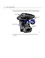
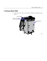
Страница 80: ...Chapter 2 Hardware Installation 2 21 2 Remove the Core Module from the Fixed Angle Mount 16397...
Страница 132: ...Chapter 3 Setup 3 23 5 Move the cursor to the Exit Menu select Save Changes Exit or Save Changes and press Enter...
Страница 154: ...Chapter 3 Setup 3 45 2 Press Enter and then select the desired setting from the drop down menu Other RS 232...
Страница 183: ...3 74 Chapter 3 Setup...
Страница 221: ...Appendix B Feature Kits B 13 3 Select Install or Update BACKPACK Driver 4 Select Finish to restart the computer...
Страница 232: ...B 24 Appendix B Feature Kits 5 Install the Antenna Cover and secure it with screws 2 16874 Wireless Antenna Cover...
Страница 249: ...Appendix B Feature Kits B 41 10 Slide the Keyboard Shelf onto the Bottom Plate and install the four screws 17372...
Страница 251: ...Appendix B Feature Kits B 43 12 Install a Strain Relief Bushing through the Mounting Bracket 18530 Strain Relief Bushing...
Страница 259: ...Appendix B Feature Kits B 51 5 Wrap the metal strap around the pole and loop it through the other end of the clamp 17356...
Страница 260: ...B 52 Appendix B Feature Kits 6 Snug the clamp and then crimp the metal strap with a pair of pliers 17357...
Страница 263: ...Appendix B Feature Kits B 55 11 Route the cables in the Wall Bracket as shown below 17359...
Страница 294: ...B 86 Appendix B Feature Kits 5 Push in the Core Module Support and lower the Core Module 6 Remove the Core Module 17345...
Страница 302: ...B 94 Appendix B Feature Kits 17729 Pole Mount Wall Mount...
Страница 311: ...Appendix B Feature Kits B 103 10 Route the cables in the Wall Bracket as shown below 17734 Mounting Screw on both sides...
Страница 326: ...B 118 Appendix B Feature Kits 2 Insert the end of the paper into the Paper Guide 16731...
Страница 328: ...B 120 Appendix B Feature Kits 4 Remove the cut paper waste from the Presenter 16965...
Страница 334: ...B 126 Appendix B Feature Kits 19050...
Страница 352: ...B 144 Appendix B Feature Kits 10 Install the CD ROM Bracket 3 screws 19232 Screws CD ROM Bracket...
Страница 366: ...Index 158 USB RS 232 port server 1 34 1 35 B 14 V Video subsystem 1 11 W Wireless LAN communications 1 12...
Страница 367: ...Index 159...
Страница 368: ...B005 0000 1254 September 2001 Printed on recycled paper...